

Evaluation of peristaltic micromixers for highly integrated microfluidic systems
- PMID: 27036809
- PMCID: PMC5848714
- DOI: 10.1063/1.4940927
Evaluation of peristaltic micromixers for highly integrated microfluidic systems
Abstract
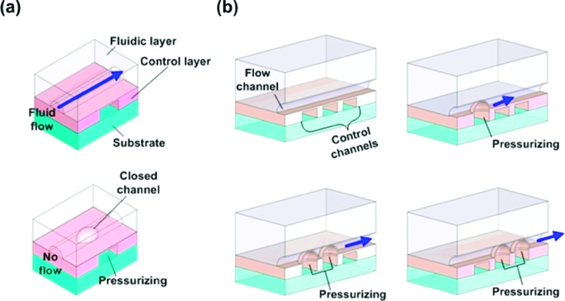
Microfluidic devices based on the multilayer soft lithography allow accurate manipulation of liquids, handling reagents at the sub-nanoliter level, and performing multiple reactions in parallel processors by adapting micromixers. Here, we have experimentally evaluated and compared several designs of micromixers and operating conditions to find design guidelines for the micromixers. We tested circular, triangular, and rectangular mixing loops and measured mixing performance according to the position and the width of the valves that drive nanoliters of fluids in the micrometer scale mixing loop. We found that the rectangular mixer is best for the applications of highly integrated microfluidic platforms in terms of the mixing performance and the space utilization. This study provides an improved understanding of the flow behaviors inside micromixers and design guidelines for micromixers that are critical to build higher order fluidic systems for the complicated parallel bio/chemical processes on a chip.
Figures


Similar articles
-
An effective splitting-and-recombination micromixer with self-rotated contact surface for wide Reynolds number range applications.Biomicrofluidics. 2013 Oct 28;7(5):54121. doi: 10.1063/1.4827598. eCollection 2013. Biomicrofluidics. 2013. PMID: 24396530 Free PMC article.
-
Integrated Vortex Micropumps and Active Micromixers in Polymer Substrates for Automating Bio-fluidic Manipulation.Conf Proc IEEE Eng Med Biol Soc. 2005;2005:1297-300. doi: 10.1109/IEMBS.2005.1616664. Conf Proc IEEE Eng Med Biol Soc. 2005. PMID: 17282433
-
A "twisted" microfluidic mixer suitable for a wide range of flow rate applications.Biomicrofluidics. 2016 Jun 27;10(3):034120. doi: 10.1063/1.4954812. eCollection 2016 May. Biomicrofluidics. 2016. PMID: 27453767 Free PMC article.
-
A Review of Microfluidic Experimental Designs for Nanoparticle Synthesis.Int J Mol Sci. 2022 Jul 27;23(15):8293. doi: 10.3390/ijms23158293. Int J Mol Sci. 2022. PMID: 35955420 Free PMC article. Review.
-
Micromixers and their applications in kinetic analysis of biochemical reactions.Talanta. 2019 Dec 1;205:120136. doi: 10.1016/j.talanta.2019.120136. Epub 2019 Jul 9. Talanta. 2019. PMID: 31450434 Review.
Cited by
-
Experimental fluid dynamics characterization of a novel micropump-mixer.Biomicrofluidics. 2020 Aug 20;14(4):044116. doi: 10.1063/5.0012240. eCollection 2020 Jul. Biomicrofluidics. 2020. PMID: 32849975 Free PMC article.
-
An integrated microfluidic platform for nucleic acid testing.Microsyst Nanoeng. 2024 May 23;10:66. doi: 10.1038/s41378-024-00677-6. eCollection 2024. Microsyst Nanoeng. 2024. PMID: 38784376 Free PMC article.
References
Publication types
MeSH terms
Grants and funding
LinkOut - more resources
Full Text Sources
Other Literature Sources