. 2016 Jun;16(6):635-9.
doi: 10.1080/14737175.2016.1175939. Epub 2016 Apr 20.

Interventional MRI-guided catheter placement and real time drug delivery to the central nervous system

Affiliations

Interventional MRI-guided catheter placement and real time drug delivery to the central nervous system

Seunggu J Han et al. Expert Rev Neurother. 2016 Jun.

Abstract

Local delivery of therapeutic agents into the brain has many advantages; however, the inability to predict, visualize and confirm the infusion into the intended target has been a major hurdle in its clinical development. Here, we describe the current workflow and application of the interventional MRI (iMRI) system for catheter placement and real time visualization of infusion. We have applied real time convection-enhanced delivery (CED) of therapeutic agents with iMRI across a number of different clinical trials settings in neuro-oncology and movement disorders. Ongoing developments and accumulating experience with the technique and technology of drug formulations, CED platforms, and iMRI systems will continue to make local therapeutic delivery into the brain more accurate, efficient, effective and safer.

Keywords: Interventional MRI; catheter placement; convection enhanced delivery; drug delivery; real time.


Figures

Figure 1
Figure 1. Patient positioning
The patient’s head is fixed in an MRI compatible Mayfield fixation device attached to the MRI table. The prone position is also possible with elevation of the head off of the bottom of the bore.
Figure 2
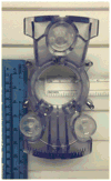
Figure 2. SmartGrid for localizing the entry point
The localizing adhesive grid (SmartGrid) is placed over the approximate region of the preplanned entry site. The ClearPoint software generates an entry point within the SmartGrid for the entry site. Image courtesy of MRI Interventions.
Figure 3
Figure 3. Skull mounted SmartFrame
The SmartFrame houses a gadolinium impregnanted fluid stem within the infusion cannula guide. This allows the software to automatically detect the trajectory of the cannula.
Figure 4
Figure 4. SmartFrame adjustments made in the 4 axes for target trajectory
Detecting the fluid stem allows the software to guide the alignment of the cannula guide to the target trajectory via adjustments made on the X–Y translational and the pitch-roll axes by knobs built into the frame. These adjustments can also be made using hand controllers extending out to the opening of the MRI bore for easy access to the neurosurgeon. Image courtesy of MRI Interventions.
Figure 5
Figure 5. Scalp mounted SmartFrame
This frame is able to mount directly onto the scalp through screws that puncture the scalp and secure onto the skull. At the entry point of the cannula, only a stab incision is made through the scalp, and a hand twist drill is used along the chosen trajectory to create a burr hole.
Figure 6
Figure 6. The infusion cannula connected to a MRI compatible pump
The catheter is connected to a syringe mounted on a MRI compatible infusion pump away from the sterile field.
Figure 7
Figure 7. SmartFlow cannula advanced and positioned for infusion
For the depth, the software generates the distance from the top of the guide stem (orange shaft) to the target, and a depth stop (black ring with red roll screw) is secured at this exact distance along the catheter (off white). After visualizing the fluid flow from the cannula tip, the cannula is then advanced through the guide tube into the brain to the target depth. Then the locking screw (clear with white roll screw) on the guide stem locks the infusion catheter at the target depth and the infusion is started.
Figure 8
Figure 8. Real time visualization of infusion
T1 MR images obtained during infusion demonstrates the co-infused gadoteridol that can be seen at the tip of the catheter. The gadolinium impregnated fluid stem and tip in the guide tube can also be detected to guide trajectory planning.

References

    1. Kunwar S, Prados MD, Chang SM, et al. Direct intracerebral delivery of cintredekin besudotox (IL13-PE38QQR) in recurrent malignant glioma: a report by the Cintredekin Besudotox Intraparenchymal Study Group. J Clin Oncol. 2007;25(7):837–844. doi: 10.1200/JCO.2006.08.1117. - DOI - PubMed
    1. Kunwar S, Chang S, Westphal M, et al. Phase III randomized trial of CED of IL13-PE38QQR vs Gliadel wafers for recurrent glioblastoma. Neuro Oncol. 2010;12(8):871–881. doi: 10.1093/neuonc/nop054. This summarizes the results of the PRECISE trial. - DOI - PMC - PubMed
    1. Sampson JH, Archer G, Pedain C, et al. Poor drug distribution as a possible explanation for the results of the PRECISE trial. J Neurosurg. 2010;113(2):301–309. doi: 10.3171/2009.11.JNS091052. This reference highlights some of the challenges in clinical application of CED, and highlights the need for the ability to visualize infusions. - DOI - PubMed
    1. Mueller S, Polley MY, Lee B, et al. Effect of imaging and catheter characteristics on clinical outcome for patients in the PRECISE study. J Neurooncol. 2011;101(2):267–277. doi: 10.1007/s11060-010-0255-0. - DOI - PMC - PubMed
    1. Christine CW, Starr PA, Larson PS, et al. Safety and tolerability of putaminal AADC gene therapy for Parkinson disease. Neurology. 2009;73(20):1662–1669. doi: 10.1212/WNL.0b013e3181c29356. - DOI - PMC - PubMed