Review
. 2016 May 21;16(10):1720-42.
doi: 10.1039/c6lc00163g. Epub 2016 Apr 21.

The upcoming 3D-printing revolution in microfluidics

Affiliations
Review

The upcoming 3D-printing revolution in microfluidics

Nirveek Bhattacharjee et al. Lab Chip. .

Abstract

In the last two decades, the vast majority of microfluidic systems have been built in poly(dimethylsiloxane) (PDMS) by soft lithography, a technique based on PDMS micromolding. A long list of key PDMS properties have contributed to the success of soft lithography: PDMS is biocompatible, elastomeric, transparent, gas-permeable, water-impermeable, fairly inexpensive, copyright-free, and rapidly prototyped with high precision using simple procedures. However, the fabrication process typically involves substantial human labor, which tends to make PDMS devices difficult to disseminate outside of research labs, and the layered molding limits the 3D complexity of the devices that can be produced. 3D-printing has recently attracted attention as a way to fabricate microfluidic systems due to its automated, assembly-free 3D fabrication, rapidly decreasing costs, and fast-improving resolution and throughput. Resins with properties approaching those of PDMS are being developed. Here we review past and recent efforts in 3D-printing of microfluidic systems. We compare the salient features of PDMS molding with those of 3D-printing and we give an overview of the critical barriers that have prevented the adoption of 3D-printing by microfluidic developers, namely resolution, throughput, and resin biocompatibility. We also evaluate the various forces that are persuading researchers to abandon PDMS molding in favor of 3D-printing in growing numbers.


Figures
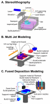
figure 1
figure 1
various 3d-printing techniques. (a) stereolithography (sl); (b) multi jet modeling (mjm); (c) fused deposition modeling (fdm, also termed “thermoplastic extrusion”)
figure 2
figure 2
sl configurations. (a) “free surface” sl technique; (b) “constrained surface” sl technique or the “bat” configuration sl printing. panels (a) and (b) are reproduced from ref. 17 with permission of the american chemical society.
figure 3
figure 3
microfluidic devices printed with sl. (a) sem micrograph of the first microfluidic device (micro-mixer) printed with sl. (below) numerical simulations of fluid mixing at the indicated cross-sections of the device. (b) sem of hollow micro-needles fabricated in e-shell-200 by dlp-sl. (c) spiral microchannel with trapezoid cross-section (printed with watershed) used for size-selective separation of bacterial cells. (d) a complex microfluidic mixer and gradient generator printed with a commercial desktop sl system. (e) a microfluidic “lobster trap” for bacteria fabricated in bovine serum albumin with multi-photon sl. (f) a colony of e.coli forming at the bottom of the “lobster trap”. panel (a) is reproduced from ref. 20 with permission of the royal society of chemistry. panel (b) is reproduced from ref. 22 with permission of the american institute of physics. panel (c) is reproduced from ref. 24 under the creative commons attribution-non commercial- noderivs 4.0 international license. panel (d) is reproduced from ref. 25 with permission of the american chemical society. panels (e) and (f) are reproduced from ref. 37 with permission of john wiley and sons.
figure 4
figure 4
microfluidic devices printed with mjm. (a) a microfluidic device printed with objet connex 350 using vero white plus as the resin, incorporating adapters for syringes, 8 channels, inlets, outlets and a port for inserting a polycarbonate membrane for cell culture. (below) side view schematic of the device. (b) a multi-flow controller device using four fluidic transistor modules, 3d-printed with a projet 3000hd printer, using visijet m3 crystal photo-plastic resin. (c) a fluid mixer and homogenizer printed with objet eden 250 using the full cure 720 resin. (d) a schematic and photo of a polyjet-printed nuclear magnetic resonance (nmr) “bubble pump”. panel (a) is reproduced from ref. 46 with permission of the american chemical society. panel (b) is reproduced from ref. 48 with permission of the royal society of chemistry. panel (c) is reproduced from ref. 49 with permission from elsevier. panel (d) is reproduced from ref. 51 with permission of the royal society of chemistry.
figure 5
figure 5
microfluidic devices printed with fdm. (a) microfluidic device used as a chemical micro-reactor, printed in poly-propylene by fdm with a 3dtouch printer. (b) microfluidic mixer for nanoparticle synthesis, printed with makerbot replicator 2x, by extruding pet and abs filaments for the device and the connectors respectively. (c) a microfluidic flow-based immuno-array for detecting protein biomarkers of cancer, printed with pla, using makerbot replicator 2x. (d) schematic drawing showing sequential printing of 350 μm wide microchannels in polycaprolactone, a silicone sealant, and a polycaprolactone cell compartmentalization chamber to make a 3d-printed nervous-system-on-a-chip device. (e) schematic of the tri-chamber with peripheral nervous system neurons in chamber 1, schwann cells in chamber 2, and epithelial cells in chamber 3. (f) photograph of the nervous system on a chip device, 3d-printed with a custom printing system. panel (a) is reproduced from ref. 63 with permission of the royal society of chemistry. panel (b) is reproduced from ref. 65 with the permission of the american chemical society. panel (c) is reproduced from ref. 66 with permission from elsevier. panels (d)-(f) are reproduced from ref. 67 with permission of the royal society of chemistry.
figure 6
figure 6
microfluidic networks produced by molding from fdm-created scaffolds. (a) schematic of polymer extrusion, which is then removed to create a 3d microfluidic mixer. (b) optical micrograph of a complex 3d chaotic microfluidic mixer in operation. (c) casting of patterned vascular networks using an fdm-printed carbohydrate lattice network. the lattice structure is first surrounded with fibroblasts encapsulated in a fibrin-gel. endothelial cells are injected into the voids created by dissolving the lattice. (insert) endothelial (huvec) lined lumen formation surrounded by fibroblasts (10t1/2) after 9 days of culture. (d) fdm-printed sacrificial isomalt scaffold, which is then embedded in agarose for casting; the carbohydrate quickly dissolves in the agarose hydrogel and forms microchannels. panels (a) and (b) are reprinted from ref. 68 by permission from macmillan publishers ltd: nature materials, copyright 2003. panel (c) is reprinted from ref. 69 by permission from macmillan publishers ltd: nature materials, copyright 2012. panel (d) is reproduced from ref. 71 with permission of the royal society of chemistry.
figure 7
figure 7
channel resolution in 3d printing. the smallest microchannels that have been consistently printed have been fabricated with peg-da by addition of 0.6% of the opaquing agent sudan i. the figure is adapted from ref. 77 with permission of the royal society of chemistry.
figure 8
figure 8
biocompatibility of resins used in bio-printing. (a) mouse hippocampal neurons (green) and skeletal muscle myoblast cells (red) encapsulated in oma-pegma1100 hydrogels, are spatially patterned in distinct regions, with multi-material sl-printing. (b) confocal image showing human dermal fibroblast cells (red) undergoing 3d migration within a rgds-functionalized region (green) of a sl-printed peg hydrogel. (c) microclusters of the bacteria s. aureus (blue) printed within high-density populations of p. aeruginosa (green) in bsa-gelatin micro-containers (red). (d) sl-printed peg-da “biobot” structure. (e) c2c12 myoblast cells mixed with matrigel and matrix proteins deposited on the “bio-bot” structure. (f) cells formed a compact and solid muscle strip around the peg-da structure. (g) immunostaining of the cells with mf-20 (green) and dapi (blue). panel (a) is reproduced from ref. 104 with permission from wiley-vch. panel (b) is reproduced from ref. 105 with permission from elsevier. panel (c) is reproduced from ref. 107 with permission from the national academy of sciences. panels (d)-(g) have been reproduced from ref. 108 with permission of the national academy of sciences.
figure 9
figure 9
biocompatibility of 3d-printed devices. (a) fluorescence micrographs showing three parallel fdm-printed polycaprolactone microchannels, with axons (stained for tau) from superior cervical ganglion neurons growing in chamber 1 of the device shown in figure 5e. (b) fluorescence micrographs of three parallel poly-caprolactone microchannels with axon-associated schwann cells in chamber 2 of the device in figure 5e. (c) fluorescence micrograph of axon-terminals and epithelial cells (cytokeratin stained in green) in chamber 3 of the device in figure 5e. (d) toxicity profiling of different 3d-printed polymer extracts using the vertebrate zebrafish model – larvae trajectories after 5 minutes of exposure with the polymer extracts. abs—acrylonitrile butadiene styrene; pla—poly(lactic) acid; vj—visijet crystal; ws—watershed 11122xc; dv—dreve fototec 7150 clear; vc—visijet sl clear; f1—form 1 clear. (e) chinese hamster ovary (cho-k1) cells growing on sl-printed peg-da-258 surfaces. (inset) fluorescence image of cho-k1 cells stained with cell tracker green. (f) cho-k1 cells cultured on tissue-culture polystyrene surface for comparison with (e). (g) hippocampal neurons from embryonic day 18 mouse cultured on 3d-printed peg-da surfaces coated with poly-d-lysine and matrigel at div 3. panels (a)-(c) are reproduced from ref. 67 with permission of the royal society of chemistry. panel (d) is reproduced from ref. 112 with permission of the american institute of physics.
figure 10
figure 10
transparency of 3d-printed devices. (a) a transparent microfluidic channel and petri-dishes sl-printed with peg-da (mw 258). (b) watershed is a very transparent sl-resin but turns yellow after prolonged exposure to ambient light.
figure 11
figure 11
multi-material sl printing. (a) various rooks fabricated with 4 different commercially available photo-resins, using a custom-built multi-material sl-printer. (b) a 2-material sl print – the red bristles are made of an elastomeric resin. (c) nih-3t3 fibroblasts stained with different colored cell tracker dyes and encapsulated in peg-da hydrogels, sl-printed in different layers. (d) cross-sectional view of the sl printed (~500 μm) layers of encapsulated nih-3t3 cells. panel (a) is reproduced from ref. 126 with permission of the authors. panel (b) is reproduced from ref. 127 with permission of the authors. panel (c) and (d) are reproduced from ref. 96 with permission of the royal society of chemistry.
figure 12
figure 12
modular microfluidics. (a) a modular microfluidic mixer built by sl. (b) schematic assembly of different 3d-printed microfluidic blocks with metal pins to build an entire device. (c) an integrated microfluidic device for biosensing built by connecting different functional modules printed in visijet m3 crystal with projet hd 3500 plus. (d) an interconnected modular device for generating oil-in-water droplets, 3d-printed with pla using ultimaker fdm-printer. (e) a cad drawing of a t-junction droplet generator, built by mating discrete microfluidic elements, sl-printed with watershed. (f) operation of the t-junction emulsification device. (g) two dye-colored aqueous streams mixed in a 3d helical mixer, and (h) formed into droplets after getting sheared by a carrier oil phase. panel (a) is reproduced from ref. 142 with the permission of the royal society of chemistry. panel (b) and (c) are reproduced from ref. 144 with the permission of the royal society of chemistry. panel (d) is reproduced from ref. 145 under the creative commons attribution license. panel (e)-(h) are reproduced from ref. 143 with the permission of the national academy of sciences.
figure 13
figure 13
3d-printed user-friendly interfaces. (a) luer and barb connectors integrated with a microfluidic channel sl-printed with watershed. (b) a complex bioreactor with integrated inlet and outlet ports printed with sl. (c) schematic of an integrated sl-printed oxygen control insert for a 24 well plate – the inlet and outlet barbs allow perfusion of oxygen into the wells. (d) photo of an entire 24-well plate fitted with the oxygen control insert that it filled with dyes for visualization. panel (b) is reproduced from ref. 148 with the permission of american society of microbiology. panel (c) and (d) are reproduced from ref. 30 under the creative commons cc0 license.
figure 14
figure 14
3d-printed automation. (a) photograph of a sl-printed single-valve device made with watershed resin. (b) a peristaltic pump designed with three valves in sequence, during an actuation phase when only the middle valve is open. (c) photograph of an actuating switch connected to a cell-culture chamber. only the valve connected to the red dye solution is open. (d)-(g) dye-filled fluidic circuit control elements printed with visijet m3 crystal using a projet 3000 hd printer and their respective analogous electrical symbols - (d) fluidic capacitors, (e) fluidic diode, (f) fluidic transistor and (g) enhanced-gain fluidic transistor. panels (a)–(c) are reproduced from ref. 152 with the permission of the royal society of chemistry. panels (d)–(g) are reproduced from ref. 48 with the permission of the royal society of chemistry.
figure 15
figure 15
the “pumping lid”. (a) schematic of a three-cup composite pumping lid for producing three different pressures in the same device. (b) micrograph of the junction at which three channels combine to produce a heterogeneous laminar flow. (c) different composite lids (top row schematics) can be used to produce different flow profiles (middle row) that agree very well with the predictions of the flow profiles (bottom row) based on the pressures produced by the lids and the device geometry. reproduced from ref. 52 with permission of the royal society of chemistry.
figure 16
figure 16
publication trends. (a) bar-graph showing the total number of publications per year (in web of science) with keywords “3d-printing” (including “additive manufacturing”, “three-dimensional printed”, etc.) and “microfluidic” from 2000-2015. (inset) bar-graph showing the total number of publications per year (in web of science) in microfluidics in the last 5 years (2011-2015). (b) projection of the exponential growth in the number of publications in 3d-printed microfluidics, based on the recent trend (from 2012-2015).

References

    1. Becker H, Locascio LE. Talanta. 2002;56:267–287. - PubMed
    1. Sackmann EK, Fulton AL, Beebe DJ. Nature. 2014;507:181–189. - PubMed
    1. Shankar SR, Jansson DG. In: Concurrent Engineering: Contemporary Issues and Modern Design Tools. Parsaei HR, Sullivan WG, editors. Springer; US: 1993.
    1. Roy E, Galas J-C, Veres T. Lab on a chip. 2011;11:3193–3196. - PubMed
    1. Focke M, Kosse D, Müller C, Reinecke H, Zengerle R, von Stetten F. Lab on a chip. 2010;10:1365–1386. - PubMed

Publication types

MeSH terms