. 2016 Apr 29:7:11425.
doi: 10.1038/ncomms11425.

Ultraflexible organic amplifier with biocompatible gel electrodes

Affiliations

Ultraflexible organic amplifier with biocompatible gel electrodes

Tsuyoshi Sekitani et al. Nat Commun. .

Abstract

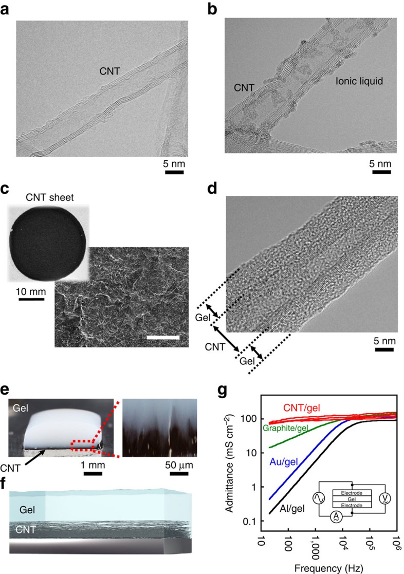
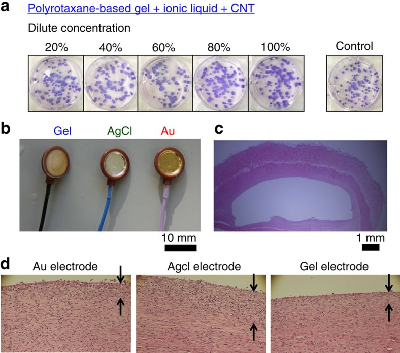
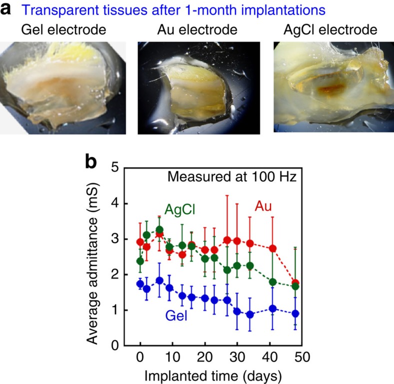
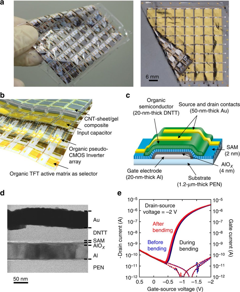
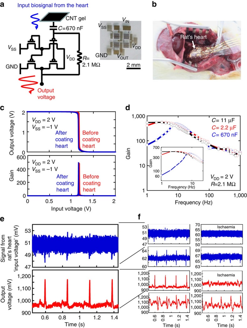
In vivo electronic monitoring systems are promising technology to obtain biosignals with high spatiotemporal resolution and sensitivity. Here we demonstrate the fabrication of a biocompatible highly conductive gel composite comprising multi-walled carbon nanotube-dispersed sheet with an aqueous hydrogel. This gel composite exhibits admittance of 100 mS cm(-2) and maintains high admittance even in a low-frequency range. On implantation into a living hypodermal tissue for 4 weeks, it showed a small foreign-body reaction compared with widely used metal electrodes. Capitalizing on the multi-functional gel composite, we fabricated an ultrathin and mechanically flexible organic active matrix amplifier on a 1.2-μm-thick polyethylene-naphthalate film to amplify (amplification factor: ∼200) weak biosignals. The composite was integrated to the amplifier to realize a direct lead epicardial electrocardiography that is easily spread over an uneven heart tissue.


Conflict of interest statement

The authors declare no competing financial interests.

Figures

Figure 1
Figure 1. Conductive gel.
High-resolution cross-sectional electron microscopy image of (a) stand-alone multiwalled CNT and (b) ionic-liquid-coated CNT. The specimen was dried in vacuum and imaged by TEM (80 kV). (c) Conductive CNT sheet and magnified picture of the surface. The scale of the SEM image is 100 μm. (d) High-resolution cross-sectional electron microscopy image of the CNT/polyrotaxane composite. (e) Cross-sectional picture of the CNT/polyrotaxane composite comprising a 50- to 100-μm-thick CNT gel layer and a 1-mm-thick polyrotaxane-gel layer. A magnified picture of the CNT/polyrotaxane interface is also shown. (f) Schematic cross-section of the conductive gel where a concentration gradient of CNT is formed in the gel. (g) Admittance (mS cm−2) of CNT/polyrotaxane gel in the vertical direction as a function of frequency, represented as red line. The admittance values of a polyrotaxane gel with different conductive layers are also shown for comparison. Polyrotaxane gel with (red) CNT, (green) graphite sheet, (blue) Au-coated film and (black) Al-coated film. The admittance was derived by subtracting the parasitic resistance in the experimental setup as open/short error compensation.
Figure 2
Figure 2. Biocompatibility test 1.
(a) Colony-forming assay for cytotoxic evaluation. (b) Implant assay in living body to evaluate long-term foreign-body response. Three probes that can change the surfaces of the electrodes were used for implantation into the hypodermal tissue of living rats for 4 weeks. (c) Pathology graft after explanting the probes and staining. (d) Magnified pictures of the surfaces of the pathology grafts. The arrows represent the depth of inflammation reaction.
Figure 3
Figure 3. Biocompatibility test 2.
(a) Samples (pathology grafts) are transferred to the final clearing solution (LUCID: nine parts thiodiethanol and one part glycerol) at room temperature. The cleaned tissues are evaluated using microscopy. Internal haemorrhage is observed in the pathology grafts where the AgCl electrode is explanted. (b) Averaged conductance of electrodes subcutaneously implanted in living rats, whose details can be seen in Supplementary Fig. 9.
Figure 4
Figure 4. Ultraflexible organic integrated circuits.
(a) Picture and (b) schematic illustration of the 1.2-μm-thick ultraflexible amplifier array comprising organic transistors. (c) Cross-sectional image and (d) high-resolution cross-sectional electron microscopy image of an organic transistor on a 1.2-μm-thick plastic substrate. (e) Electrical characteristics of an organic transistor before, during and after bending to a radius of 50 μm. The transistor is fabricated on a 1.2-μm-thick PEN substrate and 1.3-μm-thick parylene encapsulation stack. The transistor channel is located at the neutral strain position. The transistor characteristics confirm that the devices are not damaged when bent to a radius of 50 μm.
Figure 5
Figure 5. Electrocardiogram using conductive gel probes and ultraflexible organic circuit.
(a) Circuit diagram of one cell of an organic amplifier with a conductive gel for in vivo electrocardiograph comprising an organic pseudo-CMOS inverter that works as an amplifier, where VDD is the power source voltage, VSS is the tuning voltage, L is the channel length and W is the channel width. Photograph of an organic pseudo-CMOS inverter is also shown. (b) Photograph of ultraflexible circuits (pseudo-CMOS inverter) on the rat heart. (c) Characteristics of the pseudo-CMOS inverter before and after coating the rat heart. The electrical performance does not change after coating. (d) Frequency responses of the gain of an organic amplifier by varying the input capacitor (c) from 0.67 to 2.2, to 11 μF. (e). Amplification performance and (f) the magnified characteristics of the organic amplifier. (Blue line) Input signal is directly obtained from the heart where CNT conductive gel is used for the electronic interface. (Red line) Output signal is amplified using an organic amplifier. An input signal of 1.2 mV is amplified to a 220-mV output signal. A series of electrocardiograms is also shown in the right. An ischaemia-induced myocardial infarction is clearly observed. The total thickness of the cardiac electrodes is ∼1 mm, while the size is 6 mm × 6 mm, which was determined by the size of a pixel of an organic amplifier (Fig. 5 and Supplementary Fig. 16).

References

    1. Ito K. Novel cross-linking concept of polymer network: synthesis, structure, and properties of slide-ring gels with freely movable junctions. Polym. J. 39, 489–499 (2007).
    1. Kishi R. et al. Electro-conductive double-network hydrogels. J. Polym. Sci. B. Polym. Phys. 50, 790–796 (2012).
    1. Matsumoto K., Sogabe S. & Endo T. Conductive networked polymer gel electrolytes composed of poly(meth)acrylate, lithium salt, and ionic liquid. J. Polym. Sci. A. Polym. Chem. 50, 1317–1324 (2012).
    1. Mei X. & Ouyang J. Highly conductive and transparent single-walled carbon nanotube thin films fabricated by gel coating. J. Mater. Chem. 21, 17842–17849 (2011).
    1. Chung K. et al. Structural and molecular interrogation of intact biological systems. Nature 497, 332–337 (2013). - PMC - PubMed

MeSH terms