Review
. 2016 Apr 27:9:94.
doi: 10.1186/s13068-016-0508-z. eCollection 2016.

Energy-efficient biomass processing with pulsed electric fields for bioeconomy and sustainable development

Affiliations
Review

Energy-efficient biomass processing with pulsed electric fields for bioeconomy and sustainable development

Alexander Golberg et al. Biotechnol Biofuels. .

Abstract

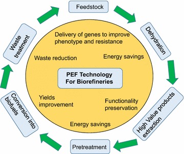
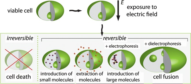
Fossil resources-free sustainable development can be achieved through a transition to bioeconomy, an economy based on sustainable biomass-derived food, feed, chemicals, materials, and fuels. However, the transition to bioeconomy requires development of new energy-efficient technologies and processes to manipulate biomass feed stocks and their conversion into useful products, a collective term for which is biorefinery. One of the technological platforms that will enable various pathways of biomass conversion is based on pulsed electric fields applications (PEF). Energy efficiency of PEF treatment is achieved by specific increase of cell membrane permeability, a phenomenon known as membrane electroporation. Here, we review the opportunities that PEF and electroporation provide for the development of sustainable biorefineries. We describe the use of PEF treatment in biomass engineering, drying, deconstruction, extraction of phytochemicals, improvement of fermentations, and biogas production. These applications show the potential of PEF and consequent membrane electroporation to enable the bioeconomy and sustainable development.

Keywords: Bioeconomy; Biorefinery; Electrobiorefinery; Electroporation; Pulsed electric fields; Sustainable development.


Figures

Fig. 1
Fig. 1
Applications of pulsed electric field (PEF) technologies for biorefineries. Pulsed electric field technology can find useful implementation in multiple processes in biorefinery. It can be used for gene transfection to improve feedstocks, save energy during drying and pretreatment, preserve functionality and specificity of the extracted high-value products, improve yields of the produced biofuels, and reduce wastes
Fig. 2
Fig. 2
E.g., of the electric field-induced transmembrane voltage (TMV). Two Chinese hamster ovary (CHO) cells in a physiological medium were exposed to the electric fields. One cell has an almost spherical geometry (left-hand sides of panels ad) and was suspended. This cell was exposed to non-porating single 50-ms, 100-V/cm pulse. The second cell is irregularly shaped and is attached (right-hand sides of panels ad). This cell was electroporated by a single 200-μs, 1000-V/cm pulse. a Membrane depolarization and hyperpolarization as detected with changes in the fluorescence of di-8-ANEPPS, a potentiometric dye reflecting the TMV. E is the strength of the electric field, p is the axes of rotational symmetry of the cell. b PEF mediated influx into the cell as detected with fluorescent dye propidium iodide (PI) as imaged 200 ms after exposure. c Measured (green) and predicted by numerical computation (gray) TMV. d PI signal. P shows a normalized arc length along the membrane Figure adapted from [28], based on [158]
Fig. 3
Fig. 3
Schematic representation of processes with cells exposed to pulsed electric fields. The possible outcomes depend on the pulsed electric field protocol (amplitude, shape, number, and duration of pulses) and additional cell manipulation techniques, e.g., (di) electrophoresis. Exposure of cells to electric fields leads to increased cell membrane permeability due to electroporation. This phenomena can be used in biorefineries for killing of cells, fusing cells, extraction or introduction of small and large molecules into the cells Figure adapted from [30]
Fig. 4
Fig. 4
a Pulsed electric field effects on the Nicotiana Tabacum L. cv bright yellow-2 cells with cell wall stained with vital dye solution (Phenosafranine). The pulsed electric field protocol: E = 2. 5 kV/cm, n = 20, f (pulse frequency) = 2 Hz, exponential pulses with duration of 400 ms. b Pulsed electric fields effects on the extracellular matrix of potato. The pulsed electric field protocol: E = 5 kV/cm, n = 20, f (pulse frequency) = 2 Hz, exponential pulses with duration of 100 ms. Tissue staining was performed with ruthenium red 5 min after PEF treatment Figure adapted from [32]
Fig. 5
Fig. 5
a Laboratory scale PEF system. Trains of two successive 2 kV 1(one) ms long pulses with opposite polarities are delivered at a 1 Hz frequency by 2 pulse generators on an array of pulsing chambers where a flow of cells is passing through at a 4 l/h rate. Measurement and control auxiliaries are indicated. b Pilot scale continuous flow (max flow rate 300 l/h) plant available at laboratory of ProdAl Scarl (University of Salerno, Italy) for PEF treatment of liquid biomass. It comprises, a DTI pulse generator (20 kV, 20 kW, square and bipolar pulses, 1–10 μs pulse width, 1–1000 Hz), four co-linear treatment chamber (0.32 cm inner diameter, 0.43 cm electrode gap), pump, heat exchanger, and storage tanks. c Pilot facility operative at KIT/IHM (Karlsruhe; Germany) for PEF treatment of dense cell suspensions at a mass flow of 400 l/h. Rectangular-shaped pulses of 65 kV and a duration of 1 µs are provided at a repetition frequency of 10 Hz, left section. The power supply is situated in the middle section. Measurement and control auxiliaries are installed in the closed right section Figure a adapted from [132]
Fig. 6
Fig. 6
a PEF treatment reactor with collinear (left panel) and parallel plate (right panel) electrode arrangement each connected to a pulse generator. The material is transported through the electrodes and tubes passing two treatment areas between high-voltage- and ground electrodes. The electric field is oriented either in direction or counter direction of the material flow. In the parallel plate electrode arrangement, the orientation of the electric field is perpendicular to the material flow. The electrode system is fed symmetrically to ground potential by a pulse generator grounded at its center point. Hence, in a substantially homogeneous medium, ground potential is established in the center of the electrode system preventing leakage currents from flowing out of the electrode system toward inlet and outlet. b PEF treatment reactor for whole sugar beets developed by KIT/IHM (digital image, left panel and schematic representation, right panel): The sugar beets are transported by means of a conveyor belt (1), to the top of a wheel equipped with electrically isolating rods (2), when rotating the wheel the rods transport the sugar beets as a package through the PEF treatment reactor. The beets are immersed into water (3), to establish an electric contact to the electrodes situated inside the PEF treatment area (4)
Fig. 7
Fig. 7
Effect PEF treatment and ethanol solvent parameters on extraction of polyphenols from grape seeds. Coupling of PEF to ethanol solvents at optimum concentration increased the total yield of polyphenols extraction Figure adapted from [99]
Fig. 8
Fig. 8
Flow process protocol for protein electroextraction from yeasts. In the lab scale pilot configuration, the volume of the pulsing chamber is set to 1.5 ml. Due to the low solution conductance, the current is only 1.2 A for the voltage of 1.8 kV needed to get the field strength of 3 kV/cm. Under the pulsing parameters (30 pulses per second with 2 × 103 µs duration), the average power is 130 kW/l. A 26 °C temperature increase is associated to the flow PEF but cooling after the treatment is fast. This explains why there is no loss of enzymatic activity in the extracted proteins Figure adapted from [129, 131]

References

    1. Zilberman D. The economics of sustainable development. Am J Agric Econ. 2013;96:385–396. doi: 10.1093/ajae/aat075. - DOI
    1. Golberg A, Vitkin E, Linshiz G, Khan SA, Hillson NJ, Yakhini Z, Yarmush ML. Proposed design of distributed macroalgal biorefineries: thermodynamics, bioconversion technology, and sustainability implications for developing economies. Biofuel Bioprod Biorefin. 2014;8:67–82. doi: 10.1002/bbb.1438. - DOI
    1. McCormick K, Kautto N. The bioeconomy in Europe: an overview. Sustainability. 2013;5:2589–2608. doi: 10.3390/su5062589. - DOI
    1. Fulton LM, Lynd LR, Körner A, Greene N, Tonachel LR. The need for biofuels as part of a low carbon energy future. Biofuel Bioprod Biorefin. 2015;9(5):454–467. doi: 10.1002/bbb.1549. - DOI
    1. Fatih Demirbas M. Biorefineries for biofuel upgrading: a critical review. Appl Energy. 2009;86:151–161. doi: 10.1016/j.apenergy.2009.04.043. - DOI