

Common 3-dimensional coordinate system for assessment of directional changes
- PMID: 27131246
- PMCID: PMC4959834
- DOI: 10.1016/j.ajodo.2015.10.021
Common 3-dimensional coordinate system for assessment of directional changes
Abstract
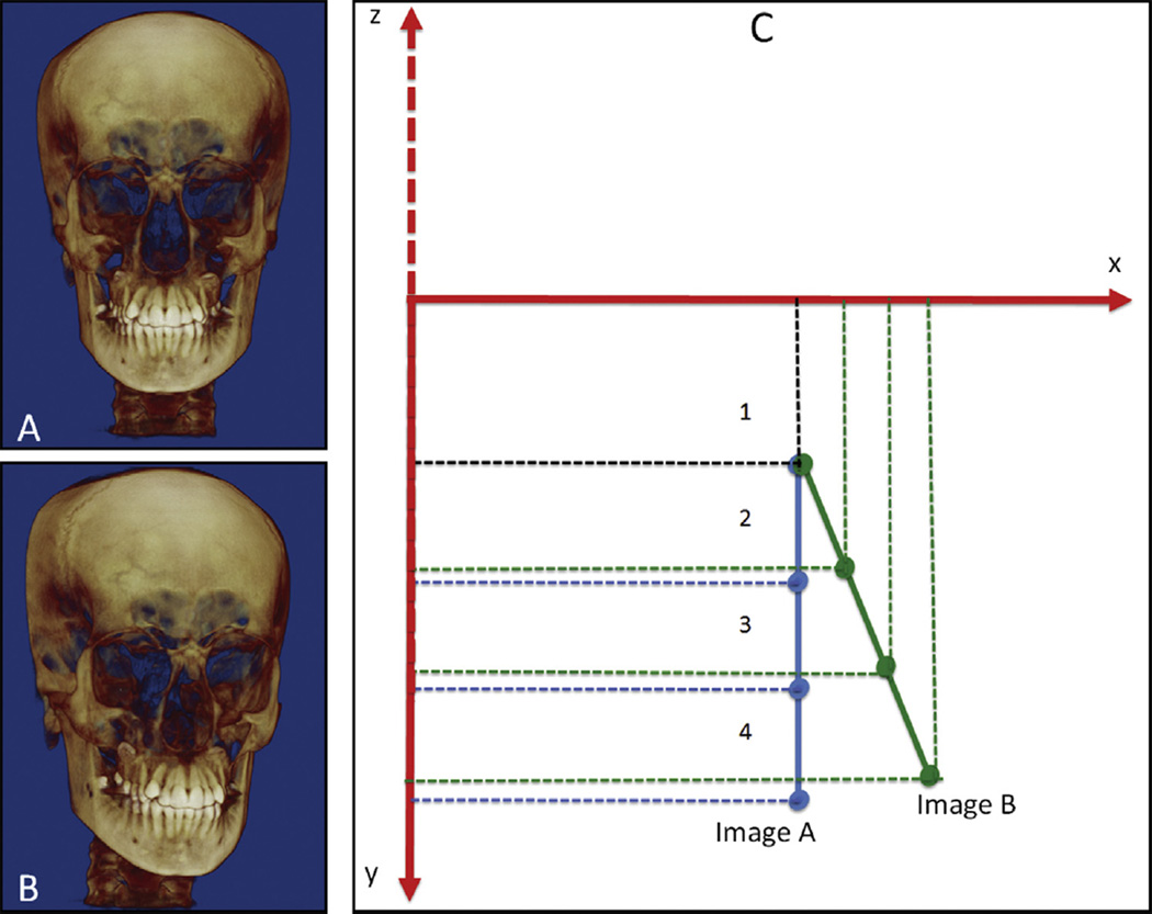
Introduction: The aims of this study were to evaluate how head orientation interferes with the amounts of directional change in 3-dimensional (3D) space and to propose a method to obtain a common coordinate system using 3D surface models.
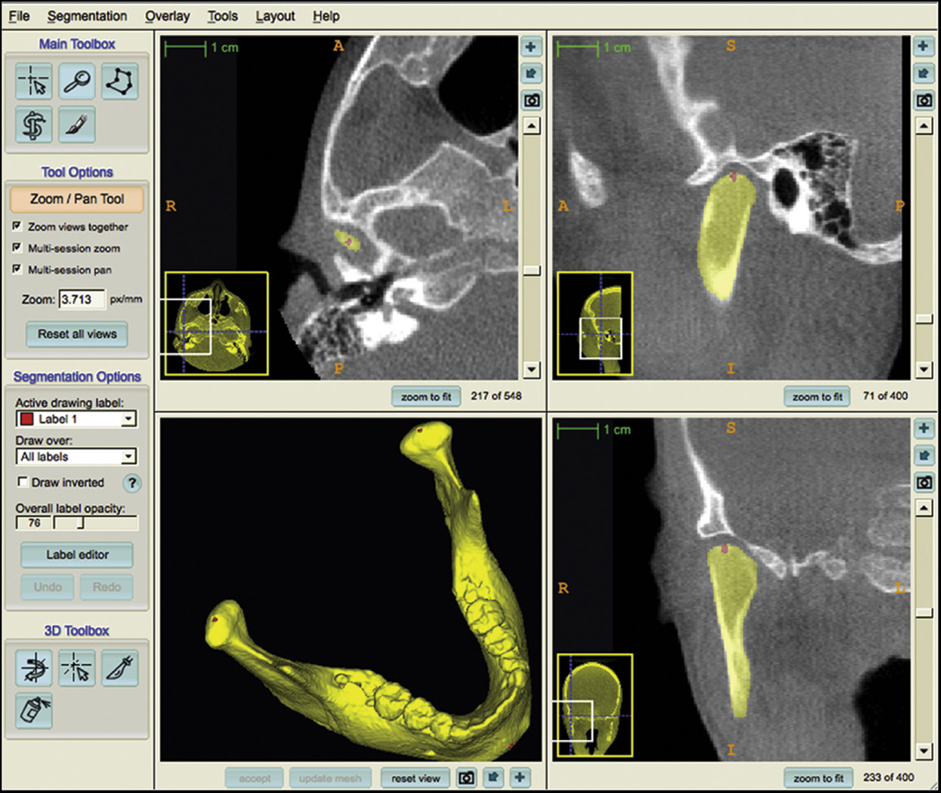
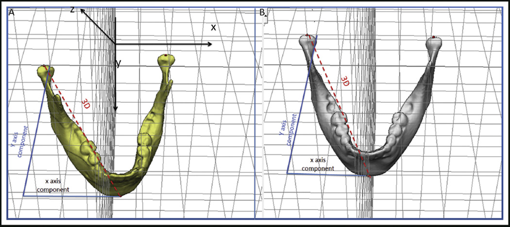
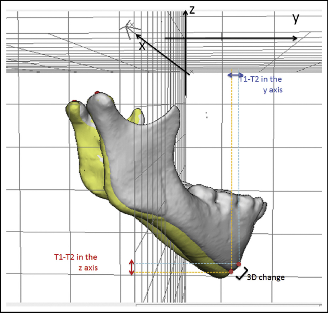
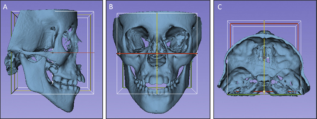
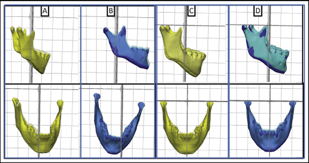
Methods: Three-dimensional volumetric label maps were built for pretreatment (T1) and posttreatment (T2) from cone-beam computed tomography images of 30 growing subjects. Seven landmarks were labeled in all T1 and T2 volumetric label maps. Registrations of T1 and T2 images relative to the cranial base were performed, and 3D surface models were generated. All T1 surface models were moved by orienting the Frankfort horizontal, midsagittal, and transporionic planes to match the axial, sagittal, and coronal planes, respectively, at a common coordinate system in the Slicer software (open-source, version 4.3.1; http://www.slicer.org). The matrix generated for each T1 model was applied to each corresponding registered T2 surface model, obtaining a common head orientation. The 3D differences between the T1 and registered T2 models, and the amounts of directional change in each plane of the 3D space, were quantified for before and after head orientation. Two assessments were performed: (1) at 1 time point (mandibular width and length), and (2) for longitudinal changes (maxillary and mandibular differences). The differences between measurements before and after head orientation were quantified. Statistical analysis was performed by evaluating the means and standard deviations with paired t tests (mandibular width and length) and Wilcoxon tests (longitudinal changes). For 16 subjects, 2 observers working independently performed the head orientations twice with a 1-week interval between them. Intraclass correlation coefficients and the Bland-Altman method tested intraobserver and interobserver agreements of the x, y, and z coordinates for 7 landmarks.
Results: The 3D differences were not affected by the head orientation. The amounts of directional change in each plane of 3D space at 1 time point were strongly influenced by head orientation. The longitudinal changes in each plane of 3D space showed differences smaller than 0.5 mm. Excellent intraobserver and interobserver repeatability and reproducibility (>99%) were observed.
Conclusions: The amount of directional change in each plane of 3D space is strongly influenced by head orientation. The proposed method of head orientation to obtain a common 3D coordinate system is reproducible.
Copyright © 2016 American Association of Orthodontists. Published by Elsevier Inc. All rights reserved.
Conflict of interest statement
All authors have completed and submitted the ICMJE Form for Disclosure of Potential Conflicts of Interest, and none were reported.
Figures
Comment in
-
Common 3-dimensional coordinate system for assessment of directional changes.Am J Orthod Dentofacial Orthop. 2016 Sep;150(3):398. doi: 10.1016/j.ajodo.2016.06.021. Am J Orthod Dentofacial Orthop. 2016. PMID: 27585764 No abstract available.
-
Authors' response.Am J Orthod Dentofacial Orthop. 2016 Sep;150(3):398-400. doi: 10.1016/j.ajodo.2016.06.020. Am J Orthod Dentofacial Orthop. 2016. PMID: 27585765 No abstract available.
References
-
- Björk A. Sutural growth of the upper face studied by the implant method. Rep Congr Eur Orthod Soc. 1964;40:49–65. - PubMed
-
- Melsen B. Effects of cervical anchorage during and after treatment: an implant study. Am J Orthod. 1978;73:526–540. - PubMed
-
- Gu Y, McNamara JA. Cephalometric superimpositions. Angle Orthod. 2008;78:967–976. - PubMed
MeSH terms
Grants and funding
LinkOut - more resources
Full Text Sources
Other Literature Sources
