

Review
doi: 10.1039/c5nr08768f.
Man-made rotary nanomotors: a review of recent developments
Affiliations
- PMID: 27152885
- PMCID: PMC4873439
- DOI: 10.1039/c5nr08768f
Item in Clipboard
Review
Man-made rotary nanomotors: a review of recent developments
Nanoscale.
.
Abstract
The development of rotary nanomotors is an essential step towards intelligent nanomachines and nanorobots. In this article, we review the concept, design, working mechanisms, and applications of state-of-the-art rotary nanomotors made from synthetic nanoentities. The rotary nanomotors are categorized according to the energy sources employed to drive the rotary motion, including biochemical, optical, magnetic, and electric fields. The unique advantages and limitations for each type of rotary nanomachines are discussed. The advances of rotary nanomotors is pivotal for realizing dream nanomachines for myriad applications including microfluidics, biodiagnosis, nano-surgery, and biosubstance delivery.
Figures
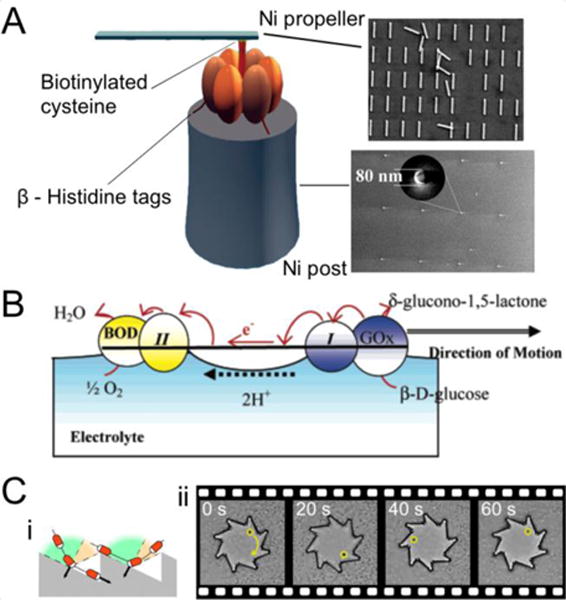
(A) A rotary nanomotor comprised of a molecular motor, a Ni propeller, and a Ni post. From Ref. . Reprinted with permission from AAAS. (B) Illustration of a bioelectrochemical motor with bilirubin oxidase (BOD) and glucose oxidase (GOx) at each end of a conducting carbon fiber. Reprinted with permission from Ref. . Copyright 2005 American Chemical Society. (C) Ratchet microgears driven by microorganisms: (i) an illustration of the collision and sliding of the microorganisms on gears and (ii) sequential micrographs showing the rotation of a microgear. Reproduced with permission from Ref. .

(A) Au microgear with Pt deposited on the steep side of the teeth. Reproduced with permission from Ref. . Copyright 2005, Wiley-VCH. (B) Overlaid sequential micrographs of a rotating Au/Ni nanorod. Reproduced from Ref. with permission from The Royal Society of Chemistry. (C) Structure and motion of rotating catalytic nanomotors composed of a Au/Pt/Au nanorod partially coated with Cr/Au. Reprinted with permission from Ref. . Copyright 2007 American Chemical Society. (D) SEM image and a schematic diagram of aPt/Au/Cr/SiO2/Cr-coated Au/Ru catalytic nanomotor rotating around its center. Reprinted with permission from Ref. . Copyright 2009 American Chemical Society. (E) Catalytic motors with a silica bead tethered to a synthetic manganese catalase. Reproduced from Ref. with permission from The Royal Society of Chemistry. (F) Dynamic shadowing growth (DSG) of the L-shaped Si/Pt catalytic motors. Reprinted with permission from Ref. . Copyright 2007 American Chemical Society. (G) Nanomotors with SiO2 heads and Pt-coated TiO2 arms. Reproduced with permission from Ref. . Copyright 2009, Wiley-VCH. (H) Self-assembled catalytic nanomotors with (i) two tadpoles consisting of SiO2 heads and Pt-coated TiO2 arms; (ii) V-shaped TiO2 rotors and SiO2 spheres. Reproduced with permission from Ref. . Copyright 2010, Wiley-VCH. (I) Schematic diagram showing the glancing angle deposition (GLAD) of a single-turn SiO2/Pt helix and the SEM image of catalytic helical microdrills obtained through the multi-step GLAD processes. Reproduced from Ref. with permission from The Royal Society of Chemistry. (J) (top) SEM images of (a) symmetric and (b and c) asymmetric rolled-up nanotubes; (middle) illustration of their motion; and (bottom) a micrograph showing the spiral trajectory of an asymmetrically rolled-up nanotube. Reprinted with permission from Ref. . Copyright 2012 American Chemical Society. (K) Diffusiophoresis nanomotors propelled by the release of K+ ions from the (Pb0.25Ba0.15Sr0.6)TiO3 (PBST) nanotubes. Reprinted with permission from Ref. . Copyright 2010, AIP Publishing LLC. (L) Schematic diagram of a ratchet-shaped Cu nanorod rotating in Br2 solution. Reprinted with permission from Ref. . Copyright 2011 American Chemical Society.
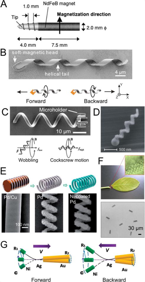
(A) NdFeB magnetic micromachine with a screw tip. Reprinted from Ref. , Copyright 2001, with permission from Elsevier. (B) SEM image of an artificial bacterial flagellum (ABF) with a Cr/Ni/Au magnetic head and a InGaAs/GaAs/Cr helix and the schematic diagrams showing its different motion modes. Reprinted with permission from Ref. . Copyright 2009, AIP Publishing LLC. (C) SEM image of a microswimmer fabricated through 3-D direct laser writing (DLW) and the illustrations of its wobbling and cockscrew motion. Reproduced with permission from Ref. . Copyright 2012, Wiley-VCH. (D) SEM image of a magnetic nanoswimmer fabricated through the GLAD of SiO2 helix followed by Co deposition. Reprinted with permission from Ref. . Copyright 2009 American Chemical Society. (E) Schematic diagrams and SEM images of a Pd/Cu nanorod, a Pd nanospring, and Ni-coated Pd nanospring obtained from template-assisted fabrication of magnetic helical nanosprings. Reproduced from Ref. with permission from The Royal Society of Chemistry. (F) Microswimmers based on the helical plant vessels. Reprinted with permission from Ref. . Copyright 2014 American Chemical Society. (G) Illustration of the forward and backward motions of magnetic nanoswimmers comprised of Ni, flexible Ag, and Au segments. Reprinted with permission from Ref. . Copyright 2010 American Chemical Society.
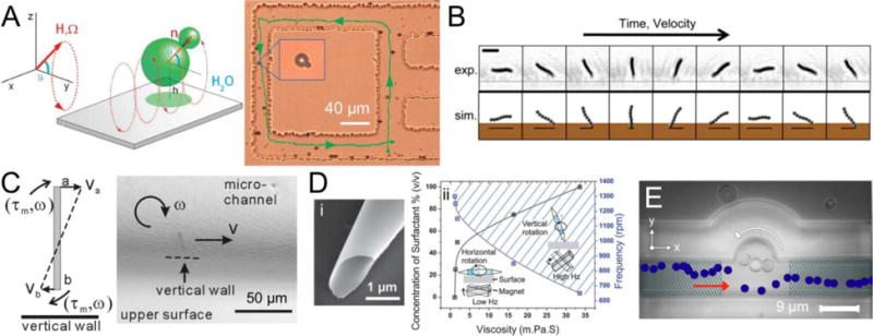
(A) Rotating paramagnetic doublet moving along grooves patterned on the substrate. Reprinted with permission from Ref. . Copyright 2008 American Chemical Society. (B) Experimental (exp.) and simulation (sim.) results of a self-assembled colloidal walker tumbling on the substrate. Reproduced from Ref. . (C) Rotating Ni nanowire moving along a vertical wall due to the asymmetric boundary conditions at each end. Reprinted with permission from Ref. . Copyright 2010 American Chemical Society. (D) (i) SEM image of a roll-up magnetic microdrill and (ii) the rotation mode of the microdrill, i.e., the horizontal or vertical rotations, at different viscosity and angular frequency. Ref. - Published by The Royal Society of Chemistry. (E) Microsphere assembly magnetically rotating counterclockwise in a microfluidic channel. The trajectory of a particle marked in blue shows the directional flow induced by the rotation. Reproduced with permission from Ref. . Copyright 2014 IOP Publishing.
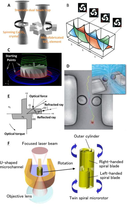
(A) The spinning calcite crystal rotated by circularly polarized laser beam compelled the rotation of SiO2 machines. Reprinted with permission from Ref. . Copyright 2001, AIP Publishing LLC. (B) Phase fronts and intensity patterns of a helical mode laser beam of azimuthal index l = 3 obtained from its interference with a plane wave. From Ref. . Reprinted with permission from AAAS. (C) A turbine-like micromotor and the resulted streamlines showing fluid circulation. Reprinted with permission from Ref. . Copyright 2012, AIP Publishing LLC. (D) Two birefringent beads simultaneously trapped and rotated in opposite directions to drive flows in a 15-μm-wide PDMS channel. Reproduced from Ref. with permission from The Royal Society of Chemistry. (E) Schematic showing the origin of the optical torque of radiation pressure micromotors. Reprinted with permission from Ref. . Copyright 1997, AIP Publishing LLC. (F) Viscous micropumps based on twin spiral micromotors driven by radiation pressure. Reprinted with permission from Ref. . Copyright 2009 Optical Society of America.
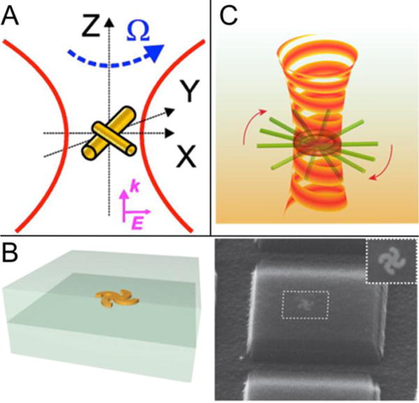
(A) Schematic diagram showing the rotation of a T-shaped Au nanorod assemblies. Reprinted with permission from Ref. . Copyright 2009 American Chemical Society. (B) Illustration and SEM image of a nanoscale plasmonic motor. Reprint by permission from Macmillan Publishers Ltd: Nature Nanotechnology Ref. , copyright 2010. (C) Illustration of an optical vortex induced rotation of a single Ag nanowire on a glass surface. Reprinted with permission from Ref. . Copyright 2013 American Chemical Society.
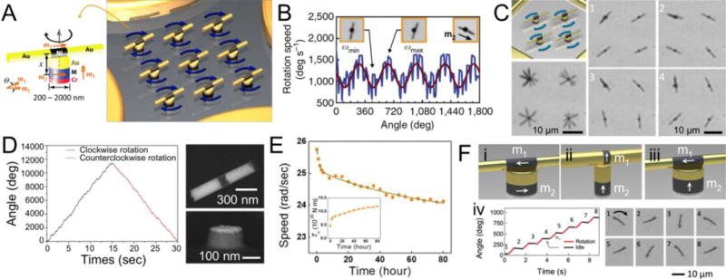
(A) Schematic diagrams of an ordered array of the nanomotors assembled from nanowires, patterned magnets and quadruple microelectrodes working as rotors, bearings, and stators. (B) Rotation speed of a nanomotor as a function of angle. (C) Illustration and sequential micrographs of a 2×2 array of nanomotors rotating simultaneously. (D) SEM images of a nanowire rotor and a patterned nanomagnet used for an ultrasmall nanomotor and its accumulative angle showing its controllability. Reproduced with permission from Ref. . (E) Evolution of the rotation speed and the magnetic torque τM of a nanomotor during its 80-hour rotation. Reproduced from Ref. with permission from The Royal Society of Chemistry. (F) Illustrations of the nanomotors with the (i) chopsticks; (ii) perpendicular; and (iii) T-shaped magnetic configurations depending on the relative magnetic orientations of the nanowires and the patterned magnets. (iv) Step-motor like angle control of the nanomotors with the T-shaped magnetic configuration. Reprinted with permission from Ref. . Copyright 2015 American Chemical Society.
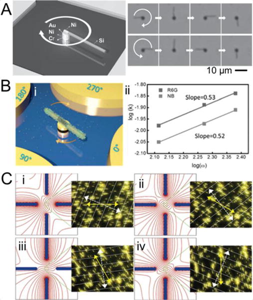
(A) Clockwise and counterclockwise rotation of Si nanomotors assembled from Si/Ni nanowire rotors on Cr/Ni/Au magnets. Reproduced with permission from Ref. . Copyright 2014, Wiley-VCH. (B) (i) Illustration of a nanomotor sensing and releasing biochemical molecules. (ii) Release rates (k) of Rhodamine-6G (R6G) and Nile Blue (NB) molecules increase with the rotation speed of the nanomotor ω (power law dependence of 0.53 and 0.52, respectively). Reproduced with permission from Ref. . Copyright 2015, Wiley-VCH. (C) Sequential optical images of Au nanowires rotating synchronously. Images on the left: electric field simulations showing equipotential lines around the electrodes; Images on the right: the yellow solid and the white dashed lines indicate orientations of the nanowires and electric field, respectively. Reprinted with permission from Ref. . Copyright 2006 American Chemical Society.
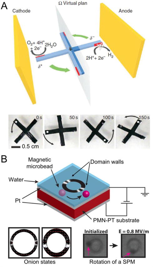
(a) Schematic diagram of a bipolar electrochemistry powered rotor and rotation of a conducting polycarbonate sheet in 50 mM HCl and in an electric field of 0.5kV m−1. The red areas are conducting and the blue areas are covered with an insulating polymer. Reprinted by permission from Macmillan Publishers Ltd: Nature Communications Ref. , copyright 2011. (B) Electric field controlled strain for rotation of the magnetic domain walls in Ni microrings, where the superparamagnetic microbeads (SPMs) attached on the microring rotate with the magnetic domain walls. Reprinted with permission from Ref. . Copyright 2015 American Chemical Society.
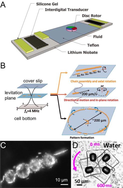
(A) Schematic diagram of a SAW-driven micromotor. Reprinted with permission from Ref. . Copyright 2011, AIP Publishing LLC. (B) Illustration of different types of linear and angular motion of AuRu nanorods on a levitation plain formed between the cover slip and the substrate in the presence of an acoustic field. Reprinted with permission from Ref. . Copyright 2012 American Chemical Society. (C) Dark field image of a chain assembly of HeLa cells rotated by ultrasonic excitation with Au nanorods attached to their surface. Reproduced with permission from Ref. . Copyright 2014, Wiley-VCH. (D) Overlaid image of sequential micrographs of acoustic-powered microswimmers rotating due to the oscillation of the asymmetrically trapped bubble. Reprinted with permission from Ref..
Similar articles
-
Electric-Field-Guided Precision Manipulation of Catalytic Nanomotors for Cargo Delivery and Powering Nanoelectromechanical Devices.ACS Nano. 2018 Feb 27;12(2):1179-1187. doi: 10.1021/acsnano.7b06824. Epub 2018 Jan 16. ACS Nano. 2018. PMID: 29303550
-
Fuel-Free Synthetic Micro-/Nanomachines.Adv Mater. 2017 Mar;29(9). doi: 10.1002/adma.201603250. Epub 2016 Dec 27. Adv Mater. 2017. PMID: 28026067 Review.
-
Recent Progress on Man-Made Inorganic Nanomachines.Small. 2015 Sep 2;11(33):4037-57. doi: 10.1002/smll.201500407. Epub 2015 Jun 26. Small. 2015. PMID: 26114572 Review.
-
Precise control of CNT-DNA assembled nanomotor using oppositely charged dual nanopores.Nanoscale. 2023 Jul 6;15(26):11052-11063. doi: 10.1039/d3nr01912h. Nanoscale. 2023. PMID: 37350160
-
Light-Powered Micro/Nanomotors.Micromachines (Basel). 2018 Jan 23;9(2):41. doi: 10.3390/mi9020041. Micromachines (Basel). 2018. PMID: 30393317 Free PMC article. Review.
Cited by
-
Metareview: a survey of active matter reviews.Eur Phys J E Soft Matter. 2025 Mar 4;48(3):12. doi: 10.1140/epje/s10189-024-00466-z. Eur Phys J E Soft Matter. 2025. PMID: 40035927 Free PMC article. Review.
-
On the shape-dependent propulsion of nano- and microparticles by traveling ultrasound waves.Nanoscale Adv. 2020 Jul 21;2(9):3890-3899. doi: 10.1039/d0na00099j. eCollection 2020 Sep 16. Nanoscale Adv. 2020. PMID: 36132771 Free PMC article.
-
Oxygen Generation Using Catalytic Nano/Micromotors.Micromachines (Basel). 2021 Oct 15;12(10):1251. doi: 10.3390/mi12101251. Micromachines (Basel). 2021. PMID: 34683302 Free PMC article. Review.
-
Acoustically propelled nano- and microcones: fast forward and backward motion.Nanoscale Adv. 2021 Oct 26;4(1):281-293. doi: 10.1039/d1na00655j. eCollection 2021 Dec 21. Nanoscale Adv. 2021. PMID: 36132955 Free PMC article.
-
Multipolar Pseudochirality-Induced Optical Torque.ACS Photonics. 2023 Sep 7;10(9):3275-3282. doi: 10.1021/acsphotonics.3c00696. eCollection 2023 Sep 20. ACS Photonics. 2023. PMID: 37743946 Free PMC article.
References
-
- Feynman RP. Eng Sci. 1960;23:22–36.
-
- Ozin GA, Manners I, Fournier-Bidoz S, Arsenault A. Adv Mater. 2005;17:3011–3018.
-
- Wang H, Pumera M. Chem Rev. 2015;115:8704–8735. - PubMed
-
- Sundararajan S, Lammert P, Zudans A, Crespi V, Sen A. Nano Lett. 2008;8:1271–1276. - PubMed
-
- Burdick J, Laocharoensuk R, Wheat PM, Posner JD, Wang J. J Am Chem Soc. 2008;130:8164–8165. - PubMed
Publication types
Grants and funding
LinkOut - more resources
Full Text Sources
Other Literature Sources