. 2016 May 18;90(4):709-23.
doi: 10.1016/j.neuron.2016.04.004. Epub 2016 May 5.

Structural Basis of Diverse Homophilic Recognition by Clustered α- and β-Protocadherins

Affiliations

Structural Basis of Diverse Homophilic Recognition by Clustered α- and β-Protocadherins

Kerry Marie Goodman et al. Neuron. .

Abstract

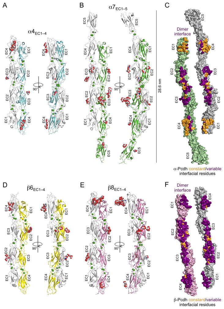
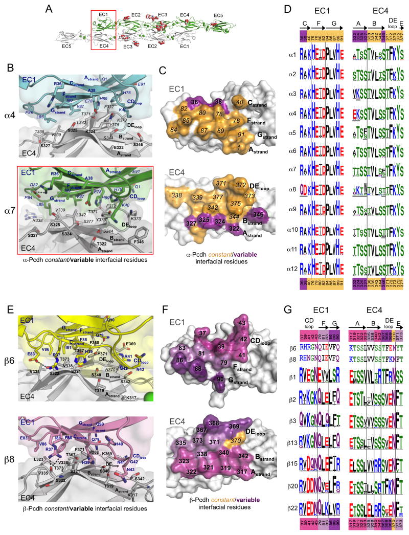
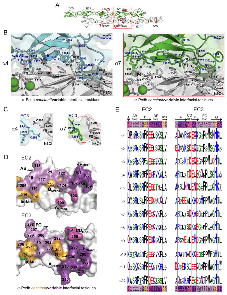
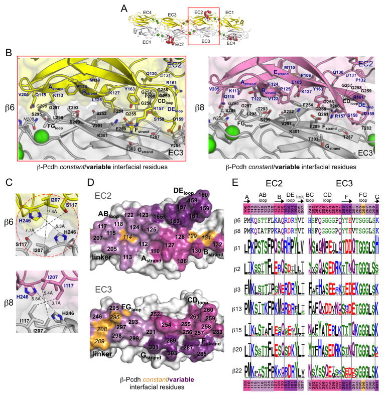
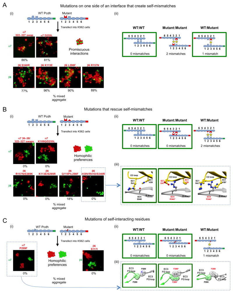
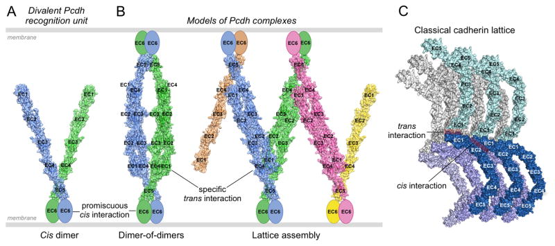
Clustered protocadherin proteins (α-, β-, and γ-Pcdhs) provide a high level of cell-surface diversity to individual vertebrate neurons, engaging in highly specific homophilic interactions to mediate important roles in mammalian neural circuit development. How Pcdhs bind homophilically through their extracellular cadherin (EC) domains among dozens of highly similar isoforms has not been determined. Here, we report crystal structures for extracellular regions from four mouse Pcdh isoforms (α4, α7, β6, and β8), revealing a canonical head-to-tail interaction mode for homophilic trans dimers comprising primary intermolecular EC1:EC4 and EC2:EC3 interactions. A subset of trans interface residues exhibit isoform-specific conservation, suggesting roles in recognition specificity. Mutation of these residues, along with trans-interacting partner residues, altered the specificities of Pcdh interactions. Together, these data show how sequence variation among Pcdh isoforms encodes their diverse strict homophilic recognition specificities, which are required for their key roles in neural circuit assembly.


Figures

Figure 1
Figure 1. Crystal structures of the α- and β-Pcdh cell-cell recognition dimers
A. Crystal structure of the α4EC1–4 dimer. The two EC1–4 protomers (colored cyan and grey) bind in a symmetrical anti-parallel configuration with EC1 interacting with EC4 and EC2 interacting with EC3. Bound calcium ions are shown as green spheres and glycans are shown as red, blue and white spheres. B. The α7EC1–5 structure, protomers colored green and grey, shows a near identical EC1–4 mediated head-to-tail dimer to α4 (RMSD = 1.9 Å). The EC5 domains extend laterally, and are therefore not involved in the dimer interaction. C. Surface representation of the two α7EC1–5 protomers, opened out to expose the dimer interface. Interfacial residues that are constant among α-Pcdhs are colored orange and those that vary among α-Pcdhs are colored purple. The interfacial residues are shown in detail in Figures 2 and 3. D. The β6EC1–4 dimer, protomers colored yellow and grey, showing a similar EC1–4 mediated head-to-tail dimer to the α-Pcdh structures (RMSD to α4EC1–4 dimer = 4.7 Å). E. The β8EC1–4 dimer (chains A and B from the crystal structure are shown), protomers colored pink and grey, is near identical to the β6EC1–4 dimer (RMSD = 1.6 Å) F. Surface representation of the two β8EC1–4 protomers, opened out to expose the dimer interface. Interfacial residues that are constant among β-Pcdhs are colored orange and those that vary between β-Pcdhs are colored purple. The interfacial residues are shown in detail in Figures 2 and 4. See also Figures S1–S3 and Tables S1–S4.
Figure 2
Figure 2. The EC1:EC4 interface is largely conserved amongst α-Pcdhs and highly diverse amongst β-Pcdhs
A. The α7EC1–5 dimer structure with the EC1:EC4 interface highlighted (red box). B. Close up of the EC1:EC4 interface in the α4EC1–4 (top, EC1 from one protomer is colored cyan the EC4 from the other protomer grey) and α7EC1–5 (bottom, EC1 green, EC4 grey) structures. Side chains are shown for all residues where the side chain contributes to the dimer interface. C. Surface representation of α7 EC1 and EC4 interfacial regions from an opened out dimer, highlighting the putative specificity-determining residues. Interfacial residues are colored orange if they are conserved amongst all α-Pcdhs and purple if they show conserved differences in one or more of the 12 α-Pcdhs (see D). D. α-Pcdh sequence logos of EC1:EC4 interface residues for each of the 12 mouse α-Pcdh isoforms, generated from sequence alignments of isoform orthologs (species used are listed in Table S5). Conserved isoform-specific residues are underlined. Secondary structure is indicated, and colors of residue numbers above and below correspond to part (C). E. Close up of the EC1:EC4 interface in the β6EC1–4 (top, EC1 yellow, EC4 grey) and β8EC1–4 (bottom, EC1 pink, EC4 grey) structures. F. Surface representation of β8 EC1 and EC4 interfacial regions from an opened out dimer, highlighting the putative specificity-determining residues. Interfacial residues are colored orange if they are conserved amongst all β-Pcdhs and shades of purple if they differ in one or more of the 22 mouse β-Pcdhs. Residues in EC1 and EC4 are colored matching shades of purple to show their predominant interaction. G. β-Pcdh sequence logos of EC1:EC4 interface residues are shown for a subset of mouse β-Pcdh isoforms (species used are listed in Table S6). The mouse β6 and β8 interface residues are shown above the logos. Secondary structure is indicated on top, and colors of residue numbers correspond to part (F). See also Figure S6 and Tables S4–S6.
Figure 3
Figure 3. Diversity in the EC2:EC3 and EC3:EC3 interfaces of α-Pcdhs
A. The α7EC1–5 dimer structure, with the EC2:EC3 interface (red box) and the EC3:EC3 interface (dashed red circle) highlighted. B. Close-up view of the EC2:EC3 interface in α4EC1–4 (left, EC2 cyan, and EC3 grey) and α7EC1–5 structures (right, EC2 in green, EC3 in grey). Side chains are shown for all residues where the side chain contributes to the dimer interface. Bound calcium ions are shown as green spheres. C. Close-up views of the EC3:EC3 interface in the α-Pcdh dimer structures. EC3 FG-loop residue 298 makes a symmetrical contact with itself in both the α4 (left, cyan and grey protomers) and α7 (right, green and grey protomers) dimers. D. Surface representation of α7 EC2 and EC3 interfacial regions from an opened out dimer, highlighting the putative specificity-determining residues. Interfacial residues are colored orange if they are conserved amongst all α-Pcdh isoforms and shades of purple if they differ in one or more of the 12 α-Pcdhs. Matching shades of purple denote EC2 and EC3 interacting residues. E. α-Pcdh sequence logos of EC2 and EC3 interface residues (species used are listed in Table S5). Secondary structure is indicated, and colors of residue numbers at top and bottom correspond to part (D). See also Tables S4–S5.
Figure 4
Figure 4. Diversity in the EC2:EC3 and center of symmetry interfaces of β-Pcdhs
A. The β6EC1–4 dimer structure, with the EC2:EC3 interface (red box) and the center of symmetry interfaces (dashed red circle) highlighted. B. Close-up view of the EC2:EC3 interface in β6EC1–4 (left, EC2 yellow, EC3 grey) and β8EC1–4 structures (right, EC2 pink, EC3 grey). Side chains are shown for all residues where the side chain contributes to the dimer interface. Bound calcium ions are shown as green spheres. C. Close-up views of the center of symmetry interfacial regions in the β6 (top, protomers yellow and grey) and β8 (bottom, protomers pink and grey) dimer structures. D. Surface representation of β8 EC2 and EC3 interfacial regions from an opened out dimer, highlighting the putative specificity-determining residues. Interfacial residues are colored orange if they are conserved amongst all β-Pcdh isoforms and shades of purple if they differ in one or more of the 22 β-Pcdhs. E. β-Pcdh sequence logos of key EC2 and EC3 interface residues are shown for a subset of the mouse β-Pcdh isoforms (species used are listed in Table S6). The mouse β6 and β8 interface residues are shown above the logos. Secondary structure is indicated, and colors of residue numbers at top and bottom correspond to part (D). See also Tables S4 and S6.
Figure 5
Figure 5. Pcdh homophilic recognition depends on trans-interacting variable residues
A. Single-sided α7 or β6 interface mutants were assayed for binding specificity in a mixed cell aggregation assay with wild-type (WT) α7 or β6. (i) Schematic of WT mVenus-tagged Pcdh and mutant mCherry-tagged Pcdh (top). Representative images of mixed cell aggregation assays are shown for each mutant (bottom). In all cases mixed aggregates were observed. The percentage of mixed (red/green) aggregates, from three independent experiments, is given below each image. (ii) Schematic illustrations of the three possible Pcdh trans dimers that can form between the interacting cells. In each case, the number of expected mismatched residues is indicated. The green boxes highlight the interactions that mediate the observed aggregates in panel (i). B. Complementary (two-sided) mutations of trans-interacting residues were introduced in α7 or β6, and binding specificity was assessed in the mixed cell aggregation assay. (i) Separate aggregates of WT and mutant Pcdh expressing cells were formed in all cases. (ii) The schematic shows that the putative mutant:WT interaction would be expected to contain two mismatched residue interactions, explaining why mixed aggregates were not observed. (iii) Structural models for the two homophilic (WT:WT and mutant:mutant) interactions that mediate the observed cell aggregates, and the putative heterophilic (WT:mutant) interface, which does not form, are shown for the β6 WT with β6 H39V/R41D/S340R mutant case. C. Mutations of residues that interact symmetrically between the two protomers. (i) Separate aggregates of WT and mutant cells were formed in all cases indicating that a new homophilic Pcdh has been generated. (ii) As in (B), homophilic preferences of WT and mutant proteins can be explained by the presence of mismatched residue interactions in the WT:mutant complex. (iii) Structural models are shown for the potential α7 WT and α7 P299F mutant complexes. See also Figure S5.
Figure 6
Figure 6. Pcdh-mediated recognition units and possible binding modes between opposed cell surfaces
A. Model of a cis-dimeric Pcdh recognition unit. The dimerization interface is located on EC6 which is depicted as an ellipse since no structure for this domain is available. Each of the two arms is taken from the 5-domain structure of α7EC1–5. The angle between them is arbitrary. The two arms are depicted in different colors since they may correspond to different isoforms. B. Models of possible Pcdh recognition complexes. The left panel depicts a dimer of recognition dimers yielding a tetrameric complex. Although the two arms are depicted here as different, the only tetramer detected so far (in solution, Rubinstein et al., 2015) has both arms identical. The right panel depicts the initiation of a linear zipper formed from different recognition units on each membrane that contain one common isoform. Mismatched isoforms, expressed by one cell but not the other, are represented in pink and yellow, and in principle would terminate growth of the intercellular Pcdh zipper. C. Classical cadherin intercellular assembly, corresponding to the extracellular structure of adherens junctions, mediated by cis and trans interactions.

References

    1. Aakre CD, Herrou J, Phung TN, Perchuk BS, Crosson S, Laub MT. Evolving New Protein-Protein Interaction Specificity through Promiscuous Intermediates. Cell. 2015;163:594–606. - PMC - PubMed
    1. Albertin CB, Simakov O, Mitros T, Wang ZY, Pungor JR, Edsinger-Gonzales E, Brenner S, Ragsdale CW, Rokhsar DS. The octopus genome and the evolution of cephalopod neural and morphological novelties. Nature. 2015;524:220–224. - PMC - PubMed
    1. Aricescu AR, Jones EY. Immunoglobulin superfamily cell adhesion molecules: zippers and signals. Curr Opin Cell Biol. 2007;19:543–50. - PubMed
    1. Chen WV, Alvarez FJ, Lefebvre JL, Friedman B, Nwakeze C, Geiman E, Smith C, Thu CA, Tapia JC, Tasic B, et al. Functional significance of isoform diversification in the protocadherin gamma gene cluster. Neuron. 2012;75:402–9. - PMC - PubMed
    1. Chen WV, Maniatis T. Clustered protocadherins. Development. 2013;140:3297–3302. - PMC - PubMed

Publication types