. 2016 Aug;89(1064):20150925.
doi: 10.1259/bjr.20150925. Epub 2016 May 10.

The vascular anatomy of the ligaments of the liver: gross anatomy, imaging and clinical applications

Affiliations

The vascular anatomy of the ligaments of the liver: gross anatomy, imaging and clinical applications

Kenji Ibukuro et al. Br J Radiol. 2016 Aug.

Abstract

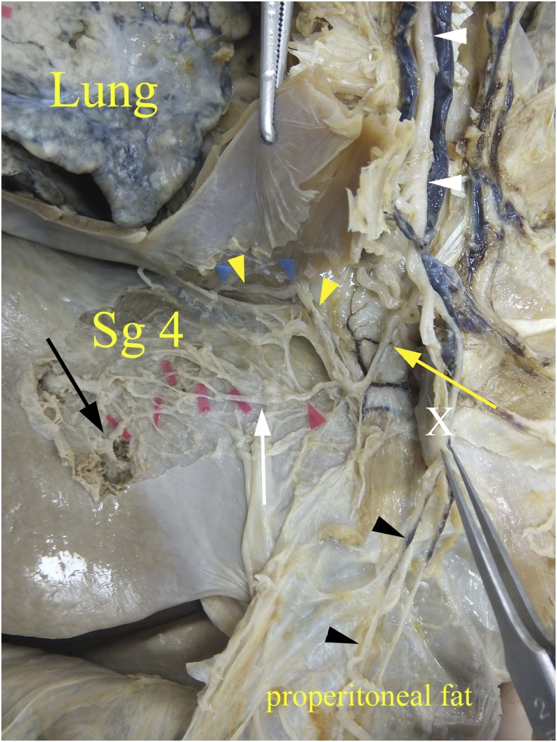
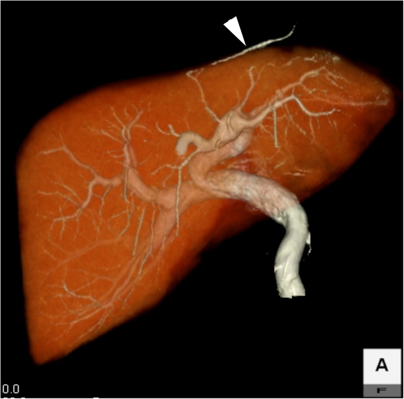
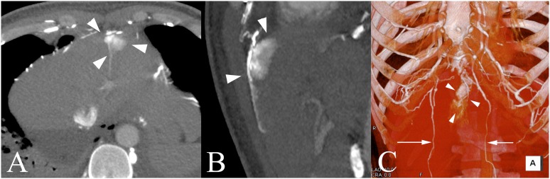
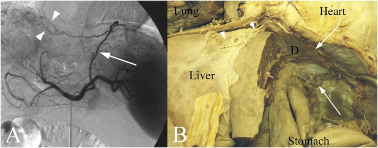
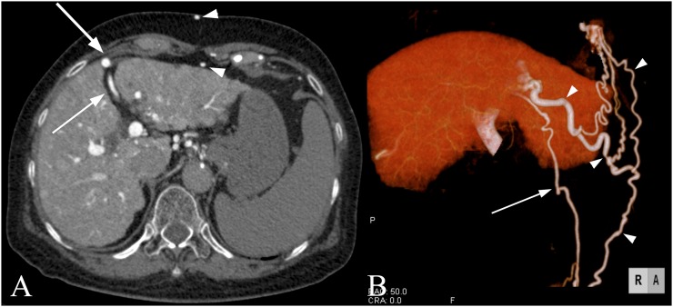
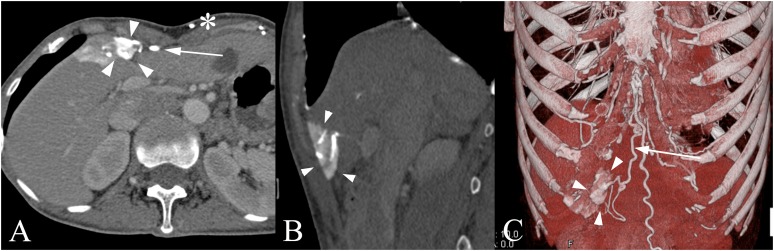
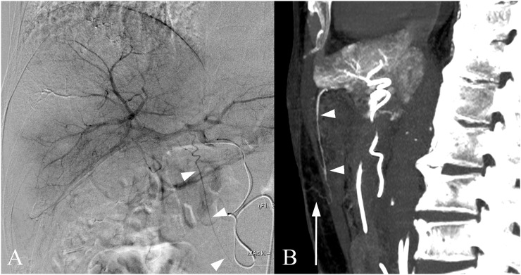
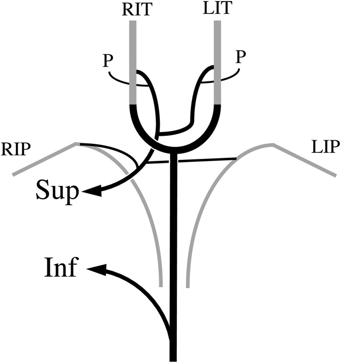
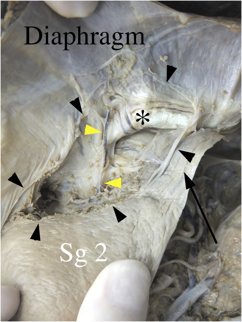
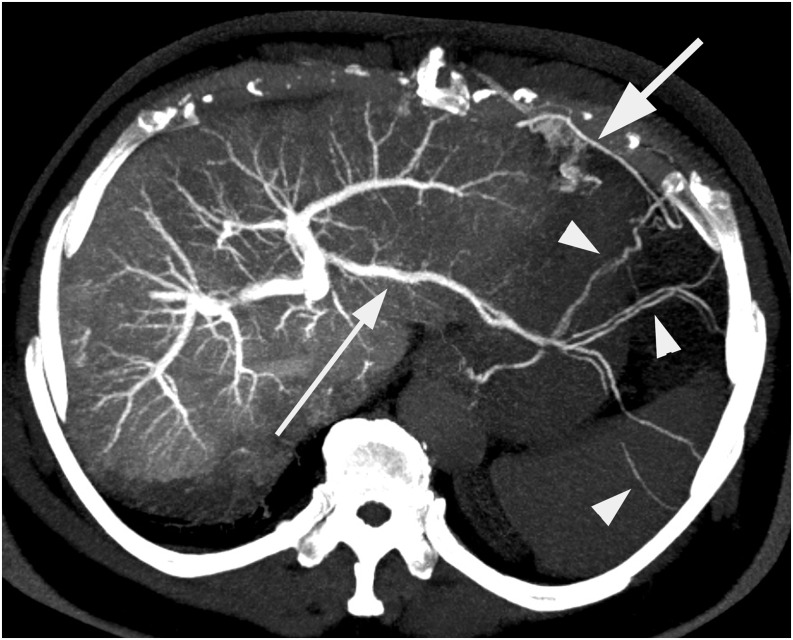
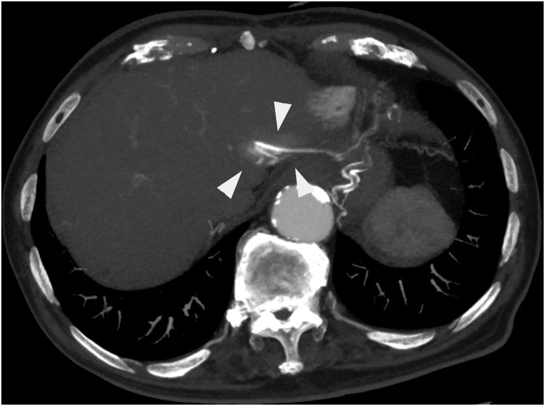
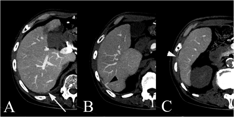
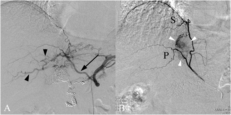
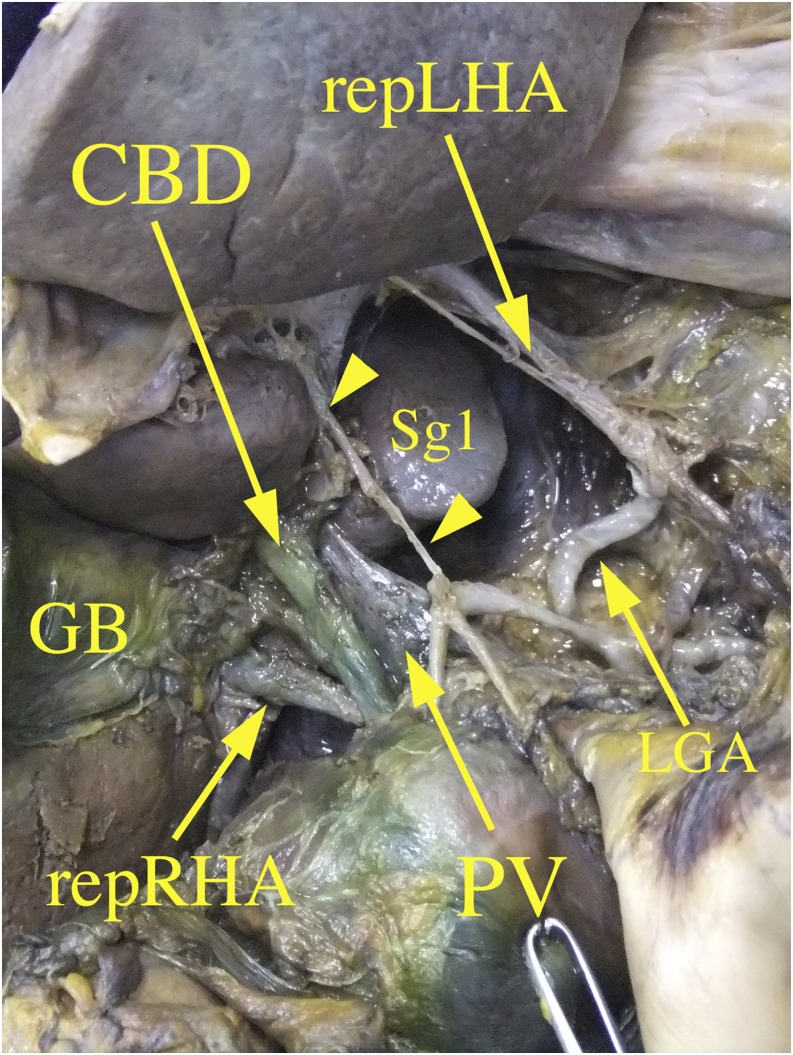
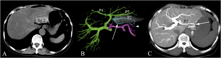
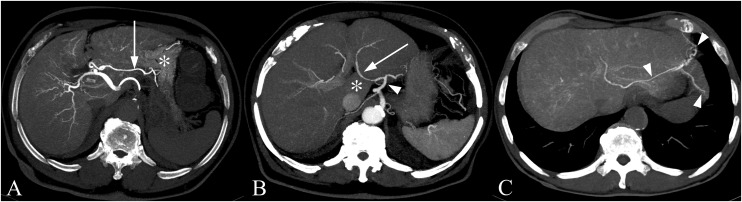
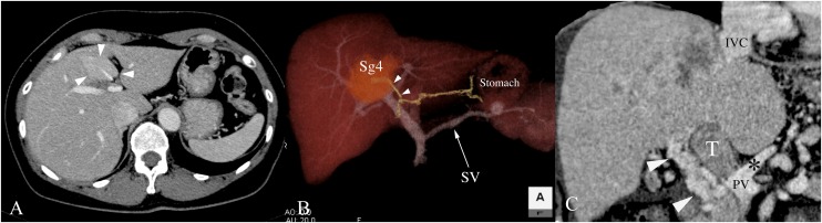
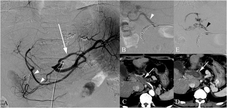
The vessels that communicate between the liver and adjacent structures require bridges between them. The bridges comprise the ligaments of the liver as follows: the falciform ligament, right and left coronary ligaments, lesser omentum including the hepatogastric ligament and hepatoduodenal ligament. Each ligament has specific communications between the intrahepatic and extrahapetic vessels. The venous communications called as the portosystemic shunt would become apparent in patients with portal hypertension, intrahepatic portal vein thrombosis and superior vena cava syndrome. The location of the venous communication is related to the pseudolesion or focal enhancement of the liver demonstrated on the CT scan. The arterial communications called collateral vascularization would become apparent in patients with hepatic artery occlusion, especially post-transhepatic arterial embolization, or in patients with the hepatic tumour abutting diaphragm. The knowledge of these collateral arteries is necessary to accomplish the effective transarterial embolization for the hepatic tumours. We reviewed the vessels in these ligaments using contrast-enhanced CT scans and angiography and discussed the clinical applications. Cadaver dissection photos were included as supplementary images for readers to recognize the actual spatial anatomy of the vessel in each ligament.


Figures

Figure 1.
Figure 1.
The falciform ligament (FL) in a cadaver: the anterior thoracic and abdominal walls were removed to show the anterior surface of the left lobe of the liver and FL. Then, the superior portion of the FL was dissected to reveal the vessels in it. The vessels (white arrow) in the superior portion of the FL anastomosed with the internal thoracic artery and vein (yellow arrow) and the inferior phrenic artery and vein (yellow arrowheads). These vessels also anastomosed with the vessel (black arrow) of the liver. The xiphoid branches (black arrowheads) were also demonstrated in the properitoneal fat. These branches anastomosed with the inferior group of vessels such as the hepatic FL artery and the paraumbilical vein. X, xiphoid process. For colour image see online.
Figure 2.
Figure 2.
A portosystemic shunt through the superior group of vein in a patient with portal hypertension: the volume-rendered image obtained by CT during arterial portography—the vessel (arrowhead) derived from the left portal vein ran towards the internal thoracic vein in the superior portion of the falciform ligament (FL). Although this portosystemic shunt is rare, the vessel is morphologically identical to the vessel in the superior portion of the FL demonstrated in Figure 1.
Figure 3.
Figure 3.
The focal enhancement of the liver through the superior group of veins in a patient with superior vena cava (SVC) syndrome. (a) The axial image of contrast-enhanced CT (CECT): the focal enhancement of the anterior aspect (arrowheads) of the left lobe of the liver was noted. The SVC was obstructed by the mediastinal invasion of lymphoma; thus, the contrast material injected through the left arm ran through the bilateral internal thoracic veins and drained into the liver via the veins of the superior portion of the falciform ligament. (b) The sagittal image of CECT: the focal enhancement was located at the superior and anterior aspect (arrowheads) of the liver. (c) The volume-rendered image: the dilated collateral vessels, such as the internal thoracic veins, intercostal veins and superior epigastric veins (arrows), were demonstrated. Focal enhancement (arrowheads) was noted at the superior and anterior aspect of the liver. Compared with Figure 6c, the xiphoid veins in the properitoneal fat were not demonstrated.
Figure 4.
Figure 4.
The pathway of the superior falciform arteries from the left inferior phrenic artery (LIPA). (a) Digital subtraction angiography of the celiac artery in a patient with the tumour located at the superior aspect of the right lobe of the liver: the dilated LIPA (arrow) ran towards the right and supplied the tumour through the superior falciform ligament (FL) arteries (arrowheads). (b) The lateral segment of the left lobe was removed and the stomach was pulled down towards the inferior to reveal the LIPA in the cadaver. The LIPA (arrows) anastomoses the superior FL arteries (arrowheads) at the superior aspect of the FL. It can be noted that this pathway is identical to the vessel demonstrated in the case of (a). D, diaphragm.
Figure 5.
Figure 5.
The recanalized umbilical vein (UV) and dilated paraumbilical veins (PUVs) in a patient with portal hypertension. (a) The axial image of CT during arterial portography: the cord-like structure (arrow) in the fissure for the falciform ligament (FL) is the recanalized UV. The dilated vein in front of this vein is the PUV (large arrowhead); its peripheral branches (arrowheads) in the properitoneal fat and subcutaneous tissue are also demonstrated in the anterior abdominal wall. (b) The volume-rendered image of the UVs and PUVs: there are two veins that run towards the anterior and inferior aspect of the abdominal wall. The PUV (arrowheads) ran anteriorly and branched off the ascending and descending veins. The xiphoid veins in the properitoneal fat drained into the internal thoracic vein. The superficial epigastric veins in the subcutaneous tissue are also demonstrated. In contrast, the recanalized UV (arrow) ran towards the umbilicus at the lower edge of the FL.
Figure 6.
Figure 6.
Focal enhancement of the liver through the inferior group of veins in a patient with left brachiocephalic vein occlusion. (a) The axial image of contrast-enhanced CT (CECT): the focal enhancement (arrowheads) was noted at the anterior aspect of the medial segment of the left lobe of the liver. The dilated xiphoid vein (arrow) in the properitoneal fat and the superficial epigastric vein (*) in the subcutaneous tissue were also demonstrated. (b) The sagittal image of CECT: the focal enhancement was located at the inferior and anterior aspect (arrowheads) of the liver. It can be noted that this was located caudal to the enhancement demonstrated in Figure 3b. (c) The volume-rendered image: the contrast material injected via the left upper arm ran into the internal thoracic vein, the xiphoid vein (arrow) in the properitoneal fat and the inferior falciform ligament vein and subsequently drained into the inferior aspect of the medial segment (arrowheads) of the left lobe of the liver.
Figure 7.
Figure 7.
The hepatic falciform ligament artery (HFLA) supplying the subcutaneous tissue in a patient with hepatocellular carcinoma. (a) Common hepatic artery angiography: the HFLA (arrowheads) derived from the left hepatic artery was identified. The characteristics of the HFLA were the downward direction from the hepatic vein towards the umbilicus and the tortuosity. (b) The sagittal image of CT hepatic arteriography: the proximal portion (arrowheads) of the HFLA runs downward behind the linea alba and branches off (arrow) distally in the subcutaneous tissue. When the chemotherapy agent was infused into the HFLA, chemical dermatitis may occur in this particular patient.
Figure 8.
Figure 8.
The schema of the vascular communication at the falciform ligament (FL). The superior group of the FL (Sup) artery and vein communicated with the internal thoracic artery and vein and the inferior phrenic artery and vein. The inferior group of FL (Inf) artery and vein such as the hepatic FL artery and the paraumbilical vein communicated with the xiphoid branch of the internal thoracic artery and vein. LIP, left inferior phrenic; LIT, left internal thoracic vessels; P, pericardial fat; RIP: right inferior phrenic arteries; RIT: right internal thoracic vessels.
Figure 9.
Figure 9.
The left triangular ligament and appendix fibrosa hepatis in a cadaver. The abdominal wall was removed and the left triangular ligament (black arrowheads) and the appendix fibrosa hepatis (arrow) were dissected. The left inferior phrenic artery and vein (*) run behind the ligament at the abdominal surface of the diaphragm and there is a small branch (yellow arrowheads) between the liver parenchyma and the left inferior phrenic vein. It can be noted that some vessels that extend from the liver can be seen in the appendix fibrosa hepatis. For colour image see online.
Figure 10.
Figure 10.
A portosystemic shunt through the left bare area in a patient with portal hypertension. In this axial image of CT during arterial portography, the superior lateral branch of the left portal vein (thin arrow) extends to the left hemidiaphragm, anastomoses with the left inferior phrenic veins (arrowheads) and subsequently drains into the left intercostal vein (thick arrow). The web-like structure is one of the features of the inferior phrenic vessels.
Figure 11.
Figure 11.
Focal enhancement of the liver through the left bare area in a patient with superior vena cava syndrome. In this axial CT image of contrast-enhanced CT, the contrast material injected via the upper arm ran into the left pericardiacophrenic vein and then the left inferior phrenic vein. The focal enhancement (arrowheads) of the posterior aspect of the left lobe of the liver was demonstrated, which was indicated by the anastomosis of the inferior phrenic vein and the intrahepatic portal vein through the left bare area.
Figure 12.
Figure 12.
A portosystemic shunt between the intrahepatic peripheral portal vein and the inferior phrenic and intercostal veins through the right bare area in a patient with portal hypertension. (a)–(c) The axial images of CT during arterial portography: the peripheral branch of the right posterior portal vein (black arrowhead) reached the posterior surface of the liver and connected with the right inferior phrenic vein (arrow) and subsequently the right intercostal vein (white arrowhead).
Figure 13.
Figure 13.
Arterial anastomosis between the intrahepatic artery and the inferior phrenic artery through the right bare area. (a) Celiac artery angiography in a patient with hepatic artery occlusion: as a hepatic artery aneurysm was embolized by the metallic coils, the proper and common hepatic arteries were occluded in this particular patient. The intrahepatic arteries (arrowheads) through the right inferior phrenic artery (RIPA) (arrow) were demonstrated. It can be noted that the RIPA and the left gastric artery make a common trunk. (b) RIPA angiography in a patient with hepatocellular carcinoma at the posterior (P) aspect of the right lobe of the liver: the tumour stain (arrowheads) was demonstrated between the P and superior (S) branches of the right inferior phrenic arteries.
Figure 14.
Figure 14.
The replaced right and left hepatic arteries in the lesser omentum in a cadaver. The membranous portion of the lesser omentum was removed. The replaced left hepatic artery (repLHA) that arises from the left gastric artery (LGA) at the upper portion of the lesser omentum (hepatogastric ligament) was demonstrated. It can be noted that the caudate lobe (Sg 1) was identified behind the replaced LHA. The middle hepatic artery (arrowheads), the portal vein (PV), the replaced right hepatic artery (repRHA) and the common bile duct (CBD) were located at the right margin of the lesser omentum (hepatoduodenal ligament). GB: gallbladder.
Figure 15.
Figure 15.
Hepatopetal and hepatofugal portal venous flow in the aberrant left gastric vein. (a) The axial image of pre-contrast-enhanced CT in a patient with focal density abnormality in the liver: the fatty change of the liver, with the exception of the lateral superior segment (Sg 2) of the left lobe of the liver, was noted. (b) The volume-rendered image of contrast-enhanced CT: the vessel (arrow) that arises from the lesser curvature of the stomach drained into Sg 2 and anastomosed with the intrahepatic portal vein (P2), which was the aberrant left gastric vein (ab-LGV). As the fat is not metabolized in the stomach, the fat content of the blood in the ab-LGV is less than that of the blood in the superior mesenteric vein (SMV). The Sg 2 is especially supplied by the ab-LGV and the other segments are supplied by the SMV in this particular case. Therefore, the difference between the Sg 2 and the others in terms of the density on CT scan is demonstrated. The accompanying artery, the left gastric artery (arrowhead) was also noted. (c) Axial image of CTAP (maximum intensity projection) in a patient with portal hypertension: the aberrant left gastric vein (arrow) that arises from P2 drained into the stomach (hepatofugal portal flow) in a patient with portal hypertension. Note that the direction of the blood flow of ab-LGV in this patient was hepatofugal, which was opposite compared with that of the flow (hepatopetal portal flow) in the patient of (a).
Figure 16.
Figure 16.
CT appearance of the arteries that run through the hepatogastric ligament. (a) The accessory left gastric artery (ac-LGA) on the axial image of CT hepatic arteriography (CTHA): the enhancement of the stomach (*) was demonstrated by the accessory left gastric artery (arrow) derived from the left hepatic artery (LHA). As the ac-LGA derives from the proximal portion of the left haptic artery, the catheter should be advanced enough to avoid the ischaemic gastric complication owing to migration of the embolic materials to the ac-LGA, during hepatic artery embolization. (b) The aberrant left hepatic artery on the axial image (maximum intensity projection) of contrast-enhanced CT: the aberrant (replaced) left hepatic artery (arrow) that arises from the left gastric artery (arrowhead) was identified in front of the caudate lobe (*). The catheter should be advanced beyond the gastric branches, when the LHA embolization is attempted. (c) The accessory left inferior phrenic artery (LIPA) on the axial image of CTHA: the distribution of the artery (arrowheads) that arises from the LHA is not the stomach but the left hemidiaphragm; thus, this artery is defined as the accessory LIPA. The embolization of the LHA with this artery may cause the ischaemic change of the left diaphragm or left shoulder pain. It can be noted that the shape of the LIPA is similar to the corresponding veins demonstrated in Figure 10.
Figure 17.
Figure 17.
Veins that run through the hepatoduodenal ligament. (a) The axial image of contrast-enhanced CT (CECT) in a patient with focal abnormal density of the liver: the inferior and posterior aspects (arrowheads) of the medial segment of the left lobe were more enhanced than other segments, and the dilated vein that drained into this area can also be noted. (b) The volume-rendered image of CECT: the right gastric vein (RGV) usually drained into the portal vein; however, this RGV (arrowheads) drained into the inferior aspect of the medial segment (Sg 4) of the left lobe. Therefore, this vein was called as the aberrant RGV. (c) The coronal image of CECT in a patient with tumour thrombus in the main portal vein. As the tumour thrombus in the intrahepatic portal vein extended into the main portal vein (T), the cavernous transformation (arrowheads) as the hepatopetal collateral portal flow developed around the common bile duct located at the right aspect of the portal vein. It can be noted that the confluence between the left gastric vein (*) and the portal vein (PV) was patent. IVC, inferior vena cava; SV: splenic vein.
Figure 18.
Figure 18.
Arteries that run through the hepatoduodenal ligament: (a) celiac artery angiography in a patient whose common hepatic artery was occluded by iatrogenic dissection. The right and left hepatic arteries were reconstituted by the right gastric artery (arrowheads) through the left gastric artery (arrow). Thus, we could perform hepatic artery chemoembolization through the gastric arteries. (b) Catheter complication in a patient with hepatic artery infusion catheter: the proper hepatic artery (white arrowhead) was demonstrated by angiography of the infusion catheter at the time of placement. (c, d) The CT scan revealed soft-tissue density (arrow) along the hepatoduodenal ligament at 2 months after the placement of infusion catheter and 2 months later, it gradually increased in size. (e) Angiography via the infusion catheter at 4 months after the placement demonstrated the extravasation (arrowhead) of the contrast material in the hepatoduodenal ligament, most likely due to the obstruction of the proper hepatic artery.

Similar articles

Cited by

References

    1. Charnsangavej C, Chuang VP, Wallace S, Soo CS, Bowers T. Angiographic classification of hepatic arterial collaterals. Radiology 1982; 144: 485–94. doi: 10.1148/radiology.144.3.6285413 - DOI - PubMed
    1. Warwick R, Williams PL, eds. Gray's anatomy. 35th edn. London, UK: Longmans; 1973. p. 178.
    1. Arey LB. Developmental Anatomy. 6th edn. Tokyo, Japan: Charles E. Tuttle Co.; 1966. pp. 279–80.
    1. Sappey MC. Thesis on the accessory portal veins. [In French.] Journal de l'anatomie et de la physiologie normales et pathologiques de l'homme et des animaux 1883; 19: 517–25.
    1. Ibukuro K, Tanaka R, Fukuda H, Abe S, Tobe K. The superior group of vessels in the falciform ligament: anatomical and radiological correlation. Surg Radiol Anat 2008; 30: 311–5. doi: 10.1007/s00276-008-0325-6 - DOI - PubMed