

The Application of Ultrasound in 3D Bio-Printing
- PMID: 27164066
- PMCID: PMC6274238
- DOI: 10.3390/molecules21050590
The Application of Ultrasound in 3D Bio-Printing
Abstract
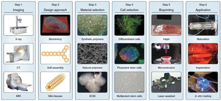
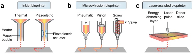
Three-dimensional (3D) bioprinting is an emerging and promising technology in tissue engineering to construct tissues and organs for implantation. Alignment of self-assembly cell spheroids that are used as bioink could be very accurate after droplet ejection from bioprinter. Complex and heterogeneous tissue structures could be built using rapid additive manufacture technology and multiple cell lines. Effective vascularization in the engineered tissue samples is critical in any clinical application. In this review paper, the current technologies and processing steps (such as printing, preparation of bioink, cross-linking, tissue fusion and maturation) in 3D bio-printing are introduced, and their specifications are compared with each other. In addition, the application of ultrasound in this novel field is also introduced. Cells experience acoustic radiation force in ultrasound standing wave field (USWF) and then accumulate at the pressure node at low acoustic pressure. Formation of cell spheroids by this method is within minutes with uniform size and homogeneous cell distribution. Neovessel formation from USWF-induced endothelial cell spheroids is significant. Low-intensity ultrasound could enhance the proliferation and differentiation of stem cells. Its use is at low cost and compatible with current bioreactor. In summary, ultrasound application in 3D bio-printing may solve some challenges and enhance the outcomes.
Keywords: bioink; bioreactor; cell spheroids; low-intensity ultrasound; three-dimensional bio-printing; ultrasound standing wave field.
Conflict of interest statement
The author declares no conflict of interest.
Figures
Similar articles
-
Replacement of Rat Tracheas by Layered, Trachea-Like, Scaffold-Free Structures of Human Cells Using a Bio-3D Printing System.Adv Healthc Mater. 2019 Apr;8(7):e1800983. doi: 10.1002/adhm.201800983. Epub 2019 Jan 11. Adv Healthc Mater. 2019. PMID: 30632706
-
Biofabrication of spatially organised tissues by directing the growth of cellular spheroids within 3D printed polymeric microchambers.Biomaterials. 2019 Mar;197:194-206. doi: 10.1016/j.biomaterials.2018.12.028. Epub 2019 Jan 8. Biomaterials. 2019. PMID: 30660995
-
Strategies for 3D bioprinting of spheroids: A comprehensive review.Biomaterials. 2022 Dec;291:121881. doi: 10.1016/j.biomaterials.2022.121881. Epub 2022 Oct 28. Biomaterials. 2022. PMID: 36335718 Review.
-
Development of Liver Decellularized Extracellular Matrix Bioink for Three-Dimensional Cell Printing-Based Liver Tissue Engineering.Biomacromolecules. 2017 Apr 10;18(4):1229-1237. doi: 10.1021/acs.biomac.6b01908. Epub 2017 Mar 21. Biomacromolecules. 2017. PMID: 28277649
-
Bioprinting Using Organ Building Blocks: Spheroids, Organoids, and Assembloids.Tissue Eng Part A. 2024 Jul;30(13-14):377-386. doi: 10.1089/ten.TEA.2023.0198. Epub 2024 Jan 25. Tissue Eng Part A. 2024. PMID: 38062998 Review.
Cited by
-
Special Issue "Biomaterials and Bioprinting".Molecules. 2016 Sep 14;21(9):1231. doi: 10.3390/molecules21091231. Molecules. 2016. PMID: 27649121 Free PMC article.
-
A Reliable Flow-Based Method for the Accurate Measure of Mass Density, Size and Weight of Live 3D Tumor Spheroids.Micromachines (Basel). 2020 Apr 28;11(5):465. doi: 10.3390/mi11050465. Micromachines (Basel). 2020. PMID: 32354148 Free PMC article.
-
In Vivo Tracking of Tissue Engineered Constructs.Micromachines (Basel). 2019 Jul 16;10(7):474. doi: 10.3390/mi10070474. Micromachines (Basel). 2019. PMID: 31315207 Free PMC article. Review.
-
A Novel Splice Variant of the Inhibitor of Growth 3 Lacks the Plant Homeodomain and Regulates Epithelial-Mesenchymal Transition in Prostate Cancer Cells.Biomolecules. 2021 Aug 4;11(8):1152. doi: 10.3390/biom11081152. Biomolecules. 2021. PMID: 34439818 Free PMC article.
-
Bioprinting Scaffolds for Vascular Tissues and Tissue Vascularization.Bioengineering (Basel). 2021 Nov 6;8(11):178. doi: 10.3390/bioengineering8110178. Bioengineering (Basel). 2021. PMID: 34821744 Free PMC article. Review.
References
-
- Murray G., Holden R. Transplantation of kidneys, experimentally and in human cases. Am. J. Surg. 1954;87:508–515. - PubMed
-
- Desmet T., Schacht E., Dubruel P. Rapid prototyping as an elegant production tool for polymeric tissue engineering scaffolds: A review. In: Barnes S.J., Harris L., editors. Tissue Engineering: Roles, Materials and Applications. Nova Science; New York, NY, USA: 2008. pp. 141–189.
-
- Bonassar L.J., Vacanti C.A. Tissue engineering: the first decade and beyond. J. Cell. Biochem. 1998;72(Suppl. S30–S31):297–303. - PubMed
Publication types
MeSH terms
LinkOut - more resources
Full Text Sources
Other Literature Sources
