

Mobile Laser Scanning Systems for Measuring the Clearance Gauge of Railways: State of Play, Testing and Outlook
- PMID: 27187400
- PMCID: PMC4883374
- DOI: 10.3390/s16050683
Mobile Laser Scanning Systems for Measuring the Clearance Gauge of Railways: State of Play, Testing and Outlook
Abstract
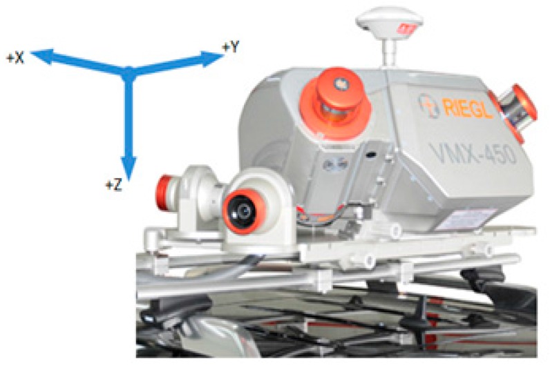
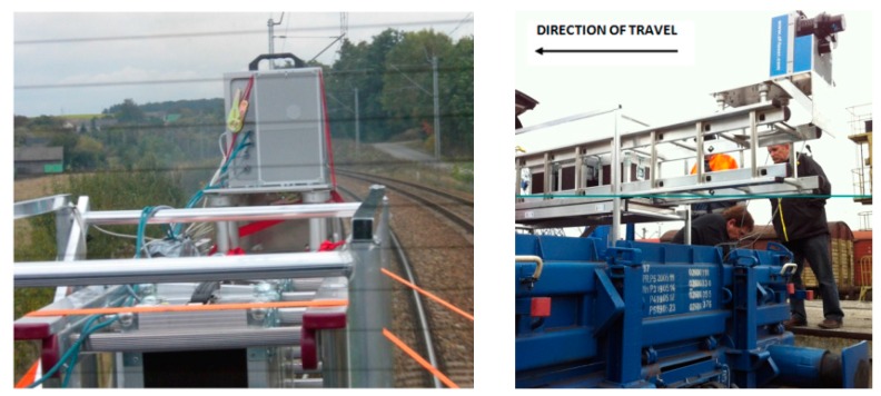
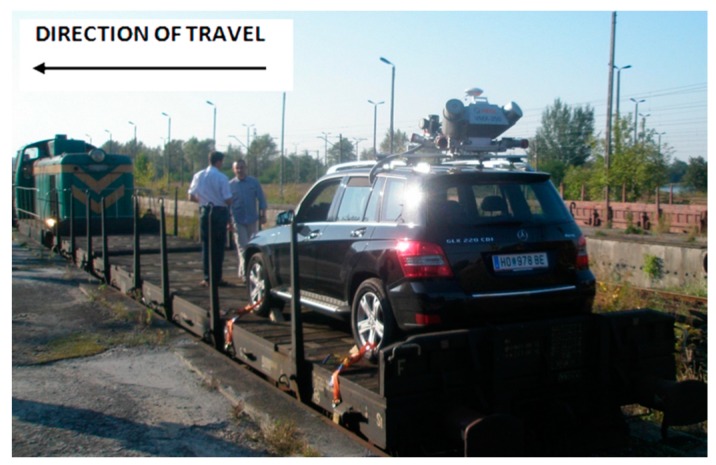
The paper contains a survey of mobile scanning systems for measuring the railway clearance gauge. The research was completed as part of the project carried out for the PKP (PKP Polish Railway Lines S.A., Warsaw, Poland) in 2011-2013. The authors conducted experiments, including a search for the latest solutions relating to mobile measurement systems that meet the basic requirement. At the very least, these solutions needed to be accurate and have the ability for quick retrieval of data. In the paper, specifications and the characteristics of the component devices of the scanning systems are described. Based on experiments, the authors did some examination of the selected mobile systems to be applied for measuring the clearance gauge. The Riegl (VMX-250) and Z+F (Zoller + Fröhlich) Solution were tested. Additional test measurements were carried out within a 30-kilometer section of the Warsaw-Kraków route. These measurements were designed so as to provide various elements of the railway infrastructure, the track geometry and the installed geodetic control network. This ultimately made it possible to reduce the time for the preparation of geodetic reference measurements for the testing of the accuracy of the selected systems. Reference measurements included the use of the polar method to select profiles perpendicular to the axis of the track. In addition, the coordinates selected were well defined as measuring points of the objects of the infrastructure of the clearance gauge. All of the tested systems meet the accuracy requirements initially established (within the range of 2 cm as required by the PKP). The tested systems have shown their advantages and disadvantages.
Keywords: database; measurement of clearance gauge; mobile laser scanning; photogrammetry.
Figures
References
-
- Mikrut S., Mikrut Z., Moskal A., Pastucha E. Detection and Recognition of Selected Class Railway Signs. Image Process. Commun. Int. J. 2014;19:83–96. doi: 10.1515/ipc-2015-0013. - DOI
-
- Briese C., Zach G., Verhoeven G., Ressl C., Ullrich A., Studnicka N., Doneus M. Analysis of mobile laser scanning data and multi-view image reconstruction; Proceedings of the International Archives of the Photogrammetry, Remote Sensing and Spatial Information Sciences, Volume XXXIX-B5, XXII ISPRS Congress; Melbourne, Australia. 25 August–1 September 2012.
-
- Chen T., Yamamoto K., Chhatkuli S., Shimamura H. Panoramic Epipolar Image Generation for Mobile Mapping System; Proceedings of the International Archives of the Photogrammetry, Remote Sensing and Spatial Information Sciences, Volume XXXIX-B5, 2012 XXII ISPRS Congress; Melbourne, Australia. 25 August–1 September 2012.
-
- Kukko A., Kaartinen H., Hyyppä J., Chen Y. Multiplatform Approach to Mobile Laser Scanning; Proceedings of the International Archives of the Photogrammetry, Remote Sensing and Spatial Information Sciences, Volume XXXIX-B5, 2012 XXII ISPRS Congress; Melbourne, Australia. 25 August–1 September 2012.
-
- Zoller+Fröhlich. [(accessed on 22 November 2015)]. Available online: http://www.zf-laser.com.
LinkOut - more resources
Full Text Sources
Other Literature Sources
