

Technical note: Computer-manufactured inserts for prosthetic sockets
- PMID: 27212209
- PMCID: PMC4931975
- DOI: 10.1016/j.medengphy.2016.04.019
Technical note: Computer-manufactured inserts for prosthetic sockets
Abstract
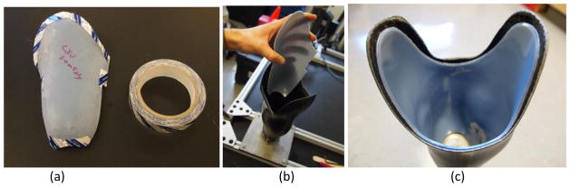
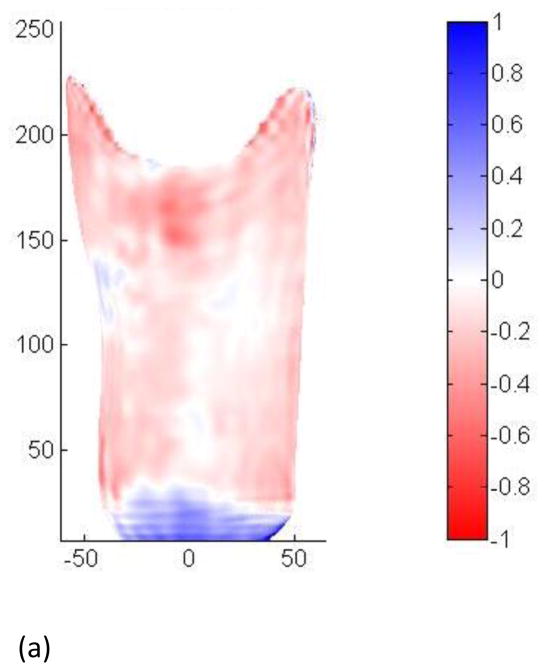
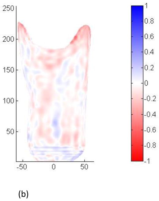
The objective of this research was to use computer-aided design software and a tabletop 3-D additive manufacturing system to design and fabricate custom plastic inserts for trans-tibial prosthesis users. Shape quality of inserts was tested right after they were inserted into participant's test sockets and again after four weeks of wear. Inserts remained properly positioned and intact throughout testing. Right after insertion the inserts caused the socket to be slightly under-sized, by a mean of 0.11mm, approximately 55% of the thickness of a nylon sheath. After four weeks of wear the under-sizing was less, averaging 0.03mm, approximately 15% of the thickness of a nylon sheath. Thus the inserts settled into the sockets over time. If existing prosthetic design software packages were enhanced to conduct insert design and to automatically generate fabrication files for manufacturing, then computer manufactured inserts may offer advantages over traditional methods in terms of speed of fabrication, ease of design, modification, and record keeping.
Keywords: Accommodation; Amputee; CAD/CAM; Residual limb; Socket; Trans-tibial; Volume loss.
Copyright © 2016 IPEM. Published by Elsevier Ltd. All rights reserved.
Conflict of interest statement
There are no competing interests.
Figures
References
-
- Saunders CG, Foort J, Bannon M, Lean D, Panych L. Computer aided design of prosthetic sockets for below-knee amputees. Prosthet Orthot Int. 1985 Apr;9(1):17–22. - PubMed
-
- Holden JM, Fernie GR. Results of the pilot phase of a clinical evaluation of computer aided design of trans-tibial prosthesis sockets. Prosthet Orthot Int. 1986 Dec;10(3):142–8. - PubMed
-
- Practice Analysis Task Force. Practice analysis of certified practitioners in the disciplines of orthotics and prosthetics. Alexandria (VA): American Board for Certification in Orthotics, Prosthetics, and Pedorthics, Inc; 2007. Available from: http://www.abcop.org/certification_/OrthotistsProsthetists/Documents_/Pr....
-
- Faustini MC, Neptune RR, Crawford RH, Rogers WE, Bosker G. An experimental and theoretical framework for manufacturing prosthetic sockets for transtibial amputees. IEEE Trans Neural Syst Rehabil Eng. 2006 Sep;14(3):304–10. - PubMed
-
- Smith DG, Burgess Em. The use of CAD/CAM technology in prosthetics and orthotics - Current clinical models and a view to the future. J Rehabil Res Dev. 2001 May-Jun;38(3):327–334. - PubMed
Publication types
MeSH terms
Grants and funding
LinkOut - more resources
Full Text Sources
Other Literature Sources
Miscellaneous
