Effects of human limb gestures on galvanic coupling intra-body communication for advanced healthcare system
- PMID: 27230849
- PMCID: PMC4882836
- DOI: 10.1186/s12938-016-0192-z
Effects of human limb gestures on galvanic coupling intra-body communication for advanced healthcare system
Abstract
Background: Intra-Body Communication (IBC), which utilizes the human body as the transmission medium to transmit signal, is a potential communication technique for the physiological data transfer among the sensors of remote healthcare monitoring system, in which the doctors are permitted to remotely access the healthcare data without interrupt to the patients' daily activities.
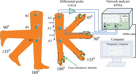
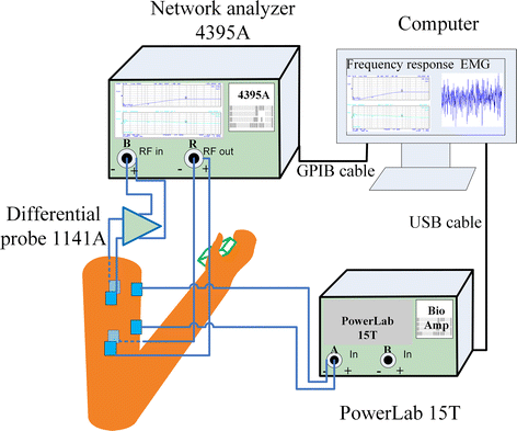
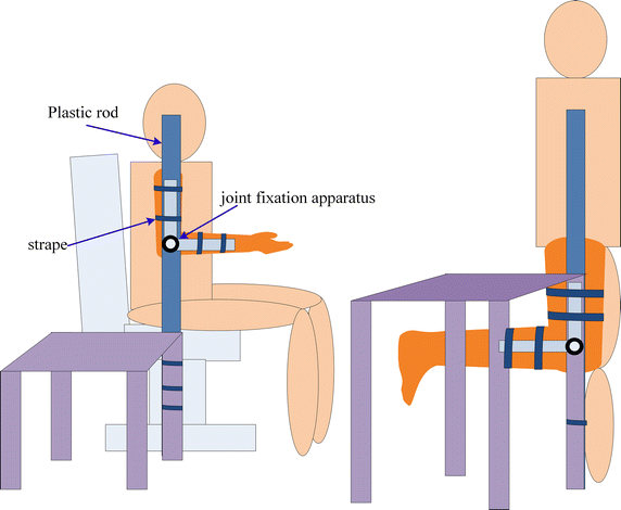
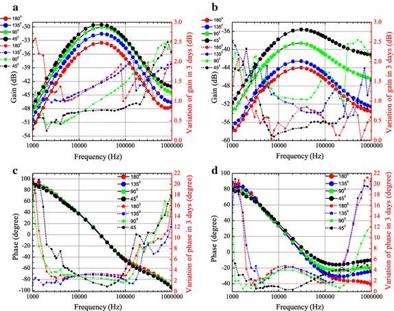
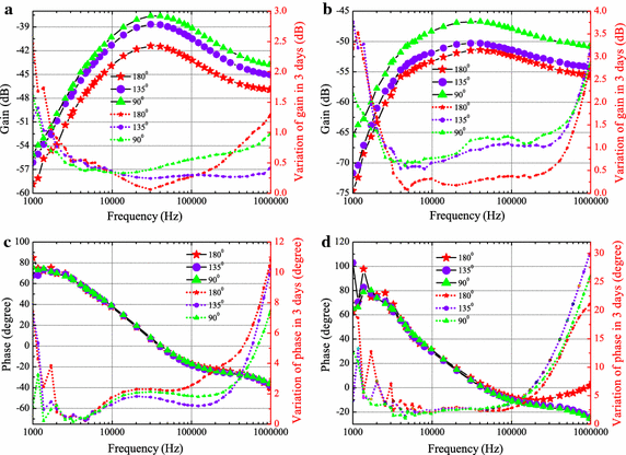
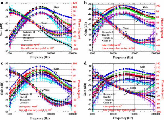
Methods: This work investigates the effects of human limb gestures including various joint angles, hand gripping force and loading on galvanic coupling IBC channel. The experiment results show that channel gain is significantly influenced by the joint angle (i.e. gain variation 1.09-11.70 dB, p < 0.014). The extension, as well as the appearance of joint in IBC channel increases the channel attenuation. While the other gestures and muscle fatigue have negligible effect (gain variation <0.77 dB, p > 0.793) on IBC channel. Moreover, the change of joint angle on human limb IBC channel causes significant variation in bit error rate (BER) performance.
Conclusions: The results reveal the dynamic behavior of galvanic coupling IBC channel, and provide suggestions for practical IBC system design.
Keywords: Bit error rate; Galvanic coupling intra-body communication; Human limb gestures; Joint angle; Muscle fatigue.
Figures

Similar articles
-
Bit error rate estimation for galvanic-type intra-body communication using experimental eye-diagram and jitter characteristics.Annu Int Conf IEEE Eng Med Biol Soc. 2013;2013:5195-8. doi: 10.1109/EMBC.2013.6610719. Annu Int Conf IEEE Eng Med Biol Soc. 2013. PMID: 24110906
-
Modeling for intra-body communication with bone effect.Annu Int Conf IEEE Eng Med Biol Soc. 2009;2009:693-6. doi: 10.1109/IEMBS.2009.5332703. Annu Int Conf IEEE Eng Med Biol Soc. 2009. PMID: 19963722
-
Limb joint effects on signal transmission in capacitive coupled intra-body communication systems.Annu Int Conf IEEE Eng Med Biol Soc. 2012;2012:6699-702. doi: 10.1109/EMBC.2012.6347531. Annu Int Conf IEEE Eng Med Biol Soc. 2012. PMID: 23367466
-
Quasi-static modeling of human limb for intra-body communications with experiments.IEEE Trans Inf Technol Biomed. 2011 Nov;15(6):870-6. doi: 10.1109/TITB.2011.2161093. Epub 2011 Jun 30. IEEE Trans Inf Technol Biomed. 2011. PMID: 21724520
-
A survey on intrabody communications for body area network applications.IEEE Trans Biomed Eng. 2013 Aug;60(8):2067-79. doi: 10.1109/TBME.2013.2254714. Epub 2013 Mar 27. IEEE Trans Biomed Eng. 2013. PMID: 23542945 Review.
Cited by
-
The Modeling and Simulation of the Galvanic Coupling Intra-Body Communication via Handshake Channel.Sensors (Basel). 2017 Apr 14;17(4):863. doi: 10.3390/s17040863. Sensors (Basel). 2017. PMID: 28420119 Free PMC article.
-
Non-Uniform Sample Assignment in Training Set Improving Recognition of Hand Gestures Dominated with Similar Muscle Activities.Front Neurorobot. 2018 Feb 12;12:3. doi: 10.3389/fnbot.2018.00003. eCollection 2018. Front Neurorobot. 2018. PMID: 29483866 Free PMC article.
-
Evaluation of Propagation Characteristics Using the Human Body as an Antenna.Sensors (Basel). 2017 Dec 11;17(12):2878. doi: 10.3390/s17122878. Sensors (Basel). 2017. PMID: 29232905 Free PMC article.
References
-
- Benhaddou D, Balakrishnan M, Yuan X. Remote healthcare monitoring system architecture using sensor networks. In: IEEE region 5 conference.Kansas City: IEEE; 2008. p. 1–6.
-
- Kirbas I, Bayilmis C. Healthface: a web-based remote monitoring interface for medical healthcare systems based on a wireless body area sensor network. J Elec Eng Comput Sci. 2012;20(4):629–638.
-
- Bazaka K, Jacob MV. Implantable devices: issues and challenges. Electronics. 2012;2(1):1–34. doi: 10.3390/electronics2010001. - DOI
-
- Halperin D, Kohno T, Heydt-Benjamin TS, Fu K, Maisel WH. Security and privacy for implantable medical devices. IEEE Pervasive Comput. 2008;7(1):30–39. doi: 10.1109/MPRV.2008.16. - DOI
-
- Pun SH. 2011. Electromagnetic sub-MHz modeling of multilayer human limb for the galvanic coupling type intra-body communication. Ph. D. thesis.
MeSH terms
LinkOut - more resources
Full Text Sources
Other Literature Sources
Medical
Miscellaneous

