

Full 3-D OCT-based pseudophakic custom computer eye model
- PMID: 27231608
- PMCID: PMC4866448
- DOI: 10.1364/BOE.7.001074
Full 3-D OCT-based pseudophakic custom computer eye model
Abstract
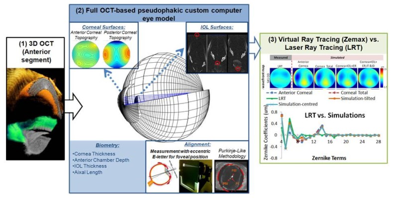
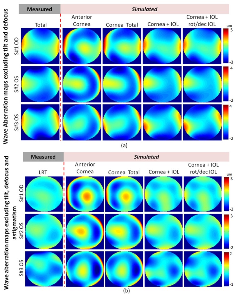
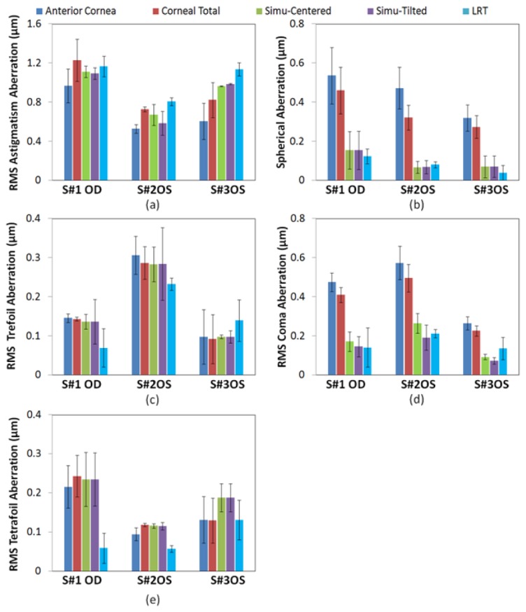
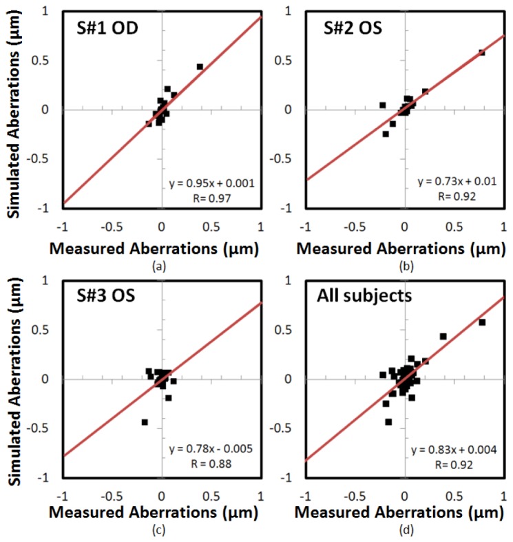
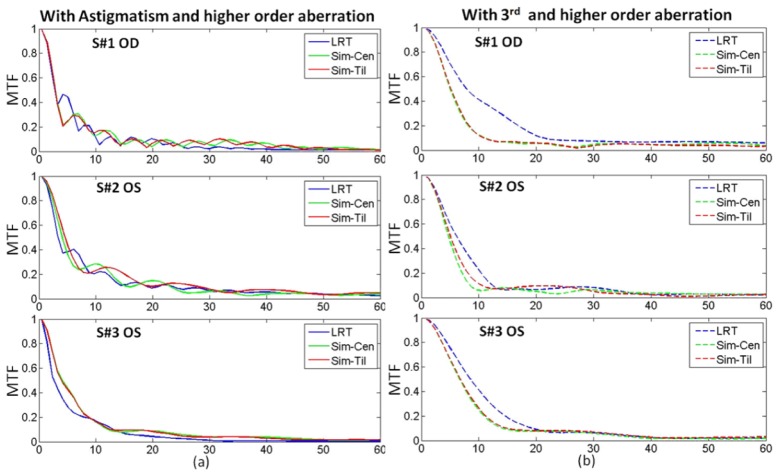
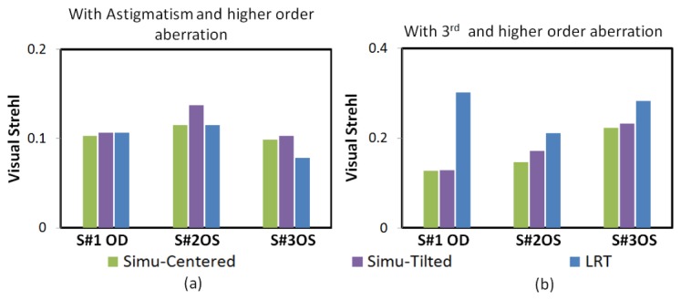
We compared measured wave aberrations in pseudophakic eyes implanted with aspheric intraocular lenses (IOLs) with simulated aberrations from numerical ray tracing on customized computer eye models, built using quantitative 3-D OCT-based patient-specific ocular geometry. Experimental and simulated aberrations show high correlation (R = 0.93; p<0.0001) and similarity (RMS for high order aberrations discrepancies within 23.58%). This study shows that full OCT-based pseudophakic custom computer eye models allow understanding the relative contribution of optical geometrical and surgically-related factors to image quality, and are an excellent tool for characterizing and improving cataract surgery.
Keywords: (110.4500) Optical coherence tomography; (200.4560) Optical data processing; (220.1010) Aberrations (global); (330.7326) Visual optics, modeling.
Figures
Similar articles
-
Customized computer models of eyes with intraocular lenses.Opt Express. 2007 Mar 5;15(5):2204-18. doi: 10.1364/oe.15.002204. Opt Express. 2007. PMID: 19532456
-
Customized aspheric intraocular lenses calculated with real ray tracing.J Cataract Refract Surg. 2009 Nov;35(11):1984-94. doi: 10.1016/j.jcrs.2009.05.053. J Cataract Refract Surg. 2009. PMID: 19878833
-
Optical quality and depth-of-field of eyes implanted with spherical and aspheric intraocular lenses.J Refract Surg. 2005 May-Jun;21(3):223-35. doi: 10.3928/1081-597X-20050501-05. J Refract Surg. 2005. PMID: 15977879
-
Intraocular lens alignment from purkinje and Scheimpflug imaging.Clin Exp Optom. 2010 Nov;93(6):400-8. doi: 10.1111/j.1444-0938.2010.00514.x. Epub 2010 Aug 25. Clin Exp Optom. 2010. PMID: 20738324 Review.
-
VioBio lab adaptive optics: technology and applications by women vision scientists.Ophthalmic Physiol Opt. 2020 Mar;40(2):75-87. doi: 10.1111/opo.12677. Epub 2020 Mar 8. Ophthalmic Physiol Opt. 2020. PMID: 32147855 Review.
Cited by
-
Testing the effect of ocular aberrations in the perceived transverse chromatic aberration.Biomed Opt Express. 2020 Jul 2;11(8):4052-4068. doi: 10.1364/BOE.396469. eCollection 2020 Aug 1. Biomed Opt Express. 2020. PMID: 32923028 Free PMC article.
-
Morphological changes of human crystalline lens in myopia.Biomed Opt Express. 2019 Nov 5;10(12):6084-6095. doi: 10.1364/BOE.10.006084. eCollection 2019 Dec 1. Biomed Opt Express. 2019. PMID: 31853387 Free PMC article.
-
Ray tracing optimization: a new method for intraocular lens power calculation in regular and irregular corneas.Sci Rep. 2023 Mar 20;13(1):4555. doi: 10.1038/s41598-023-31525-8. Sci Rep. 2023. PMID: 36941337 Free PMC article.
-
Estimation of the full shape of the crystalline lens from OCT: validation using stretched donor lenses.Biomed Opt Express. 2023 Jul 25;14(8):4261-4276. doi: 10.1364/BOE.493795. eCollection 2023 Aug 1. Biomed Opt Express. 2023. PMID: 37799671 Free PMC article.
-
Estimation of intraocular lens position from full crystalline lens geometry: towards a new generation of intraocular lens power calculation formulas.Sci Rep. 2018 Jun 29;8(1):9829. doi: 10.1038/s41598-018-28272-6. Sci Rep. 2018. PMID: 29959385 Free PMC article.
References
-
- McLellan J. S., Marcos S., Burns S. A., “Age-related changes in monochromatic wave aberrations of the human eye,” Invest. Ophthalmol. Vis. Sci. 42(6), 1390–1395 (2001). - PubMed
-
- Moreno-Barriuso E., Lloves J. M., Marcos S., Navarro R., Llorente L., Barbero S., “Ocular aberrations before and after myopic corneal refractive surgery: LASIK-induced changes measured with laser ray tracing,” Invest. Ophthalmol. Vis. Sci. 42(6), 1396–1403 (2001). - PubMed
Grants and funding
LinkOut - more resources
Full Text Sources
Other Literature Sources