

Optically monitored drug delivery patch based on porous silicon and polymer microneedles
- PMID: 27231611
- PMCID: PMC4871071
- DOI: 10.1364/BOE.7.001645
Optically monitored drug delivery patch based on porous silicon and polymer microneedles
Abstract
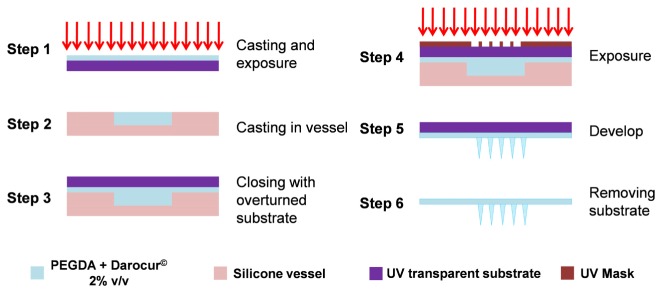
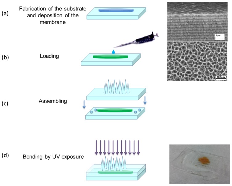
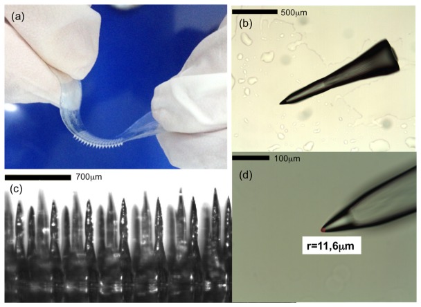
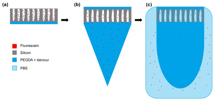
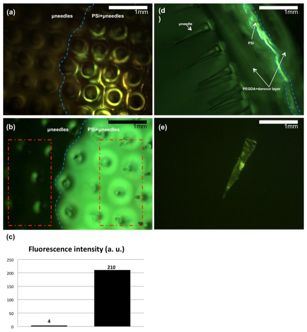
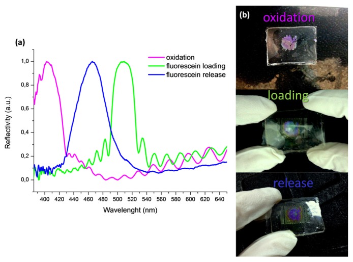
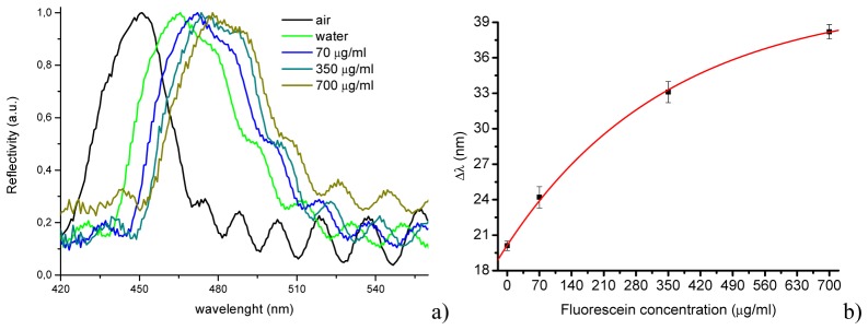
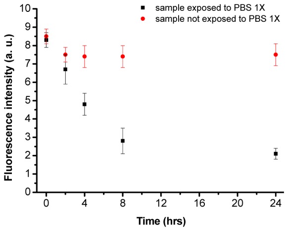
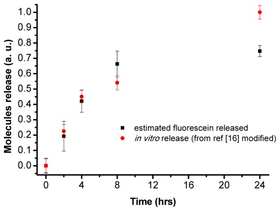
Fabrication and characterization of an optically monitored hybrid patch for local administration of drugs, based on polymeric micro-needles and a porous silicon free-standing membrane, are reported. The micro-needles are realized by an innovative photolithographic approach that allows fine tuning of geometrical parameters, using polyethylene glycol and a commercial photo-catalyzer. The porous silicon multilayer not only increases the storage of a relevant amount of the drug, but also offers a continuous, naked-eye monitoring of the drug delivery process. As a proof-of-concept experiment, we report our results on the release of a dye molecule (fluorescein, 332 Da) in a phosphate saline buffer.
Keywords: (160.5470) Polymers; (170.0170) Medical optics and biotechnology; (310.6845) Thin film devices and applications.
Figures
Similar articles
-
A Photolithographic Approach to Polymeric Microneedles Array Fabrication.Materials (Basel). 2015 Dec 11;8(12):8661-8673. doi: 10.3390/ma8125484. Materials (Basel). 2015. PMID: 28793736 Free PMC article.
-
Metallic microneedles with interconnected porosity: A scalable platform for biosensing and drug delivery.Acta Biomater. 2018 Oct 15;80:401-411. doi: 10.1016/j.actbio.2018.09.007. Epub 2018 Sep 8. Acta Biomater. 2018. PMID: 30201432
-
Recent advances in the design of polymeric microneedles for transdermal drug delivery and biosensing.Lab Chip. 2017 Apr 11;17(8):1373-1387. doi: 10.1039/c7lc00016b. Lab Chip. 2017. PMID: 28352876 Review.
-
Bioresorbable, Miniaturized Porous Silicon Needles on a Flexible Water-Soluble Backing for Unobtrusive, Sustained Delivery of Chemotherapy.ACS Nano. 2020 Jun 23;14(6):7227-7236. doi: 10.1021/acsnano.0c02343. Epub 2020 May 18. ACS Nano. 2020. PMID: 32401016 Free PMC article.
-
Lipid-polymer hybrid nanoparticles as a new generation therapeutic delivery platform: a review.Eur J Pharm Biopharm. 2013 Nov;85(3 Pt A):427-43. doi: 10.1016/j.ejpb.2013.07.002. Epub 2013 Jul 17. Eur J Pharm Biopharm. 2013. PMID: 23872180 Review.
Cited by
-
Detection of β-Lactoglobulin by a Porous Silicon Microcavity Biosensor Based on the Angle Spectrum.Sensors (Basel). 2022 Mar 1;22(5):1912. doi: 10.3390/s22051912. Sensors (Basel). 2022. PMID: 35271059 Free PMC article.
-
One-Shot Fabrication of Polymeric Hollow Microneedles by Standard Photolithography.Polymers (Basel). 2021 Feb 9;13(4):520. doi: 10.3390/polym13040520. Polymers (Basel). 2021. PMID: 33572383 Free PMC article.
-
Integrated Photodetectors Based on Group IV and Colloidal Semiconductors: Current State of Affairs.Micromachines (Basel). 2020 Sep 8;11(9):842. doi: 10.3390/mi11090842. Micromachines (Basel). 2020. PMID: 32911711 Free PMC article. Review.
-
Translation of Polymeric Microneedles for Treatment of Human Diseases: Recent Trends, Progress, and Challenges.Pharmaceutics. 2021 Jul 24;13(8):1132. doi: 10.3390/pharmaceutics13081132. Pharmaceutics. 2021. PMID: 34452093 Free PMC article. Review.
-
Biomaterials for Regenerative Medicine in Italy: Brief State of the Art of the Principal Research Centers.Int J Mol Sci. 2022 Jul 26;23(15):8245. doi: 10.3390/ijms23158245. Int J Mol Sci. 2022. PMID: 35897825 Free PMC article. Review.
References
-
- Mukerjee E. V., Collins S. D., Isseroff R. R., Smith R. L., “Microneedle array for transdermal biological fluid extraction and in situ analysis,” Sens. Actuators A Phys. 114(2-3), 267–275 (2004).10.1016/j.sna.2003.11.008 - DOI
-
- Miller P. R., Skoog S. A., Edwards T. L., Lopez D. M., Wheeler D. R., Arango D. C., Xiao X., Brozik S. M., Wang J., Polsky R., Narayan R. J., “Multiplexed Microneedle-based Biosensor Array for Characterization of Metabolic Acidosis,” Talanta 88, 739–742 (2012).10.1016/j.talanta.2011.11.046 - DOI - PMC - PubMed
LinkOut - more resources
Full Text Sources
Other Literature Sources
Research Materials