. 2016 Jul 7;16(13):2450-8.
doi: 10.1039/c6lc00565a. Epub 2016 May 31.

High density 3D printed microfluidic valves, pumps, and multiplexers

Affiliations

High density 3D printed microfluidic valves, pumps, and multiplexers

Hua Gong et al. Lab Chip. .

Abstract

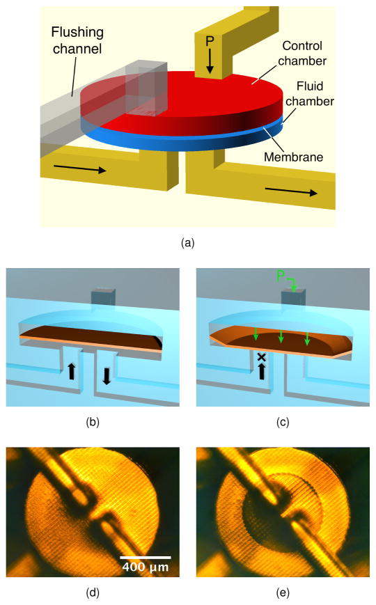
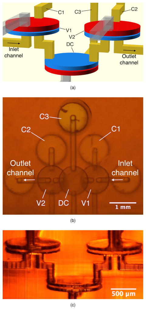
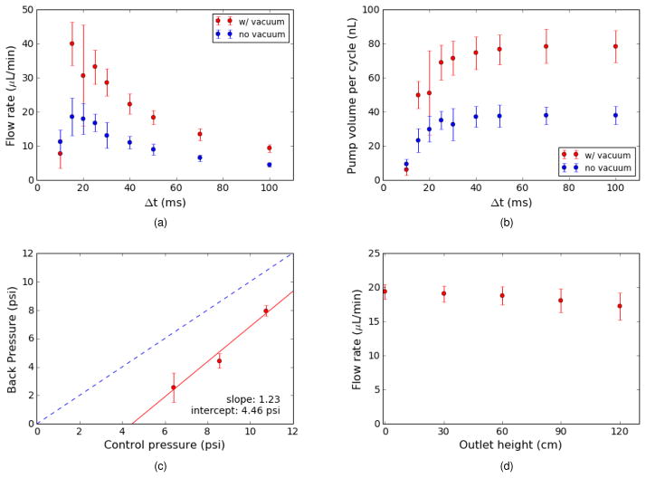
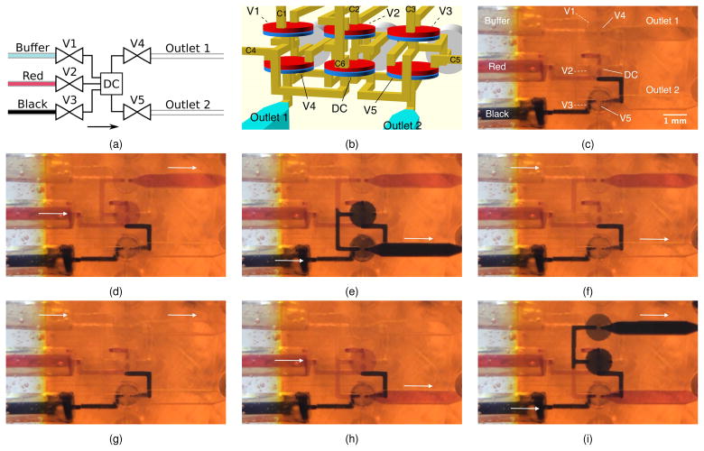
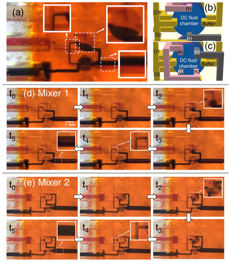
In this paper we demonstrate that 3D printing with a digital light processor stereolithographic (DLP-SLA) 3D printer can be used to create high density microfluidic devices with active components such as valves and pumps. Leveraging our previous work on optical formulation of inexpensive resins (RSC Adv., 2015, 5, 106621), we demonstrate valves with only 10% of the volume of our original 3D printed valves (Biomicrofluidics, 2015, 9, 016501), which were already the smallest that have been reported. Moreover, we show that incorporation of a thermal initiator in the resin formulation along with a post-print bake can dramatically improve the durability of 3D printed valves up to 1 million actuations. Using two valves and a valve-like displacement chamber (DC), we also create compact 3D printed pumps. With 5-phase actuation and a 15 ms phase interval, we obtain pump flow rates as high as 40 μL min(-1). We also characterize maximum pump back pressure (i.e., maximum pressure the pump can work against), maximum flow rate (flow rate when there is zero back pressure), and flow rate as a function of the height of the pump outlet. We further demonstrate combining 5 valves and one DC to create a 3-to-2 multiplexer with integrated pump. In addition to serial multiplexing, we also show that the device can operate as a mixer. Importantly, we illustrate the rapid fabrication and test cycles that 3D printing makes possible by implementing a new multiplexer design to improve mixing, and fabricate and test it within one day.


Figures

Fig. 1
Fig. 1
(CAD design of (a) for a 3D printed membrane valve. Schematic illustration and microscope photos of (b), (d) open and (c), (e) closed valves. The microscope photos show the bottom of the valve. See text for details.
Fig. 2
Fig. 2
(a) CAD design of 3D printed pump. C1–C3 connect to external pressure sources. The partially transparent channels are flushing channels for the valve control chambers, which are later sealed with epoxy. (b) Bottom view of a 3D printed pump. See text for details. (c) Side view photograph of 3D printed pump in (b).
Fig. 3
Fig. 3
(a) Maximum flow rate (zero back pressure) as a function of the phase interval, Δt. (b) Fluid volume expelled by pump for a single pump cycle calculated from the data in (a). 9 pumps were tested with vacuum and 5 without. The large error bars for vacuum at 20 ms are due to 2 pumps having significantly smaller flow rates than the others. (c) Maximum back pressure as a function of control pressure (average and standard deviation for 7 pumps). (d) Flow rate as a function of the outlet height for a control pressure of 9 psi (average and standard deviation for 6 pumps). Different pumps were used in all tests.
Fig. 4
Fig. 4
(a) Multiplexer schematic diagram. (b) CAD design taking advantage of stacked layout flexibility enabled by 3D printing. Valve labeling is the same as (a) with corresponding control lines labeled C1, C2, etc. (c) Bottom view of multiplexer fabricated according to the CAD design in (b). (d)–(i) Demonstration of arbitrary 3-to-2 multiplexing. See text for details. Arrows indicate active flow direction.
Fig. 5
Fig. 5
(a) Flow generated only by gravity. Note lack of Red/Black mixing. (b, c) Bottom view of DC channel layout in (b) Mixer 1 and (c) Mixer 2. Red channels, R1 in (b) and R1 and R2 in (c), connect the Red inlet valve (V2 in Fig. 4a) to the DC, while the black channels, B1 in (b) and B1 and B2 in (c), connect the Black inlet valve (V3) to the DC. Buffer is the channel that connects the Buffer inlet to the DC through valve V1. O1 and O2 connect the DC to Outlets 1 and 2, respectively, through valves V4 and V5. (d) and (e) compare the mixing performance of the designs in (b) and (c). See text for details.

References

    1. Rogers CI, Qaderi K, Woolley AT, Nordin GP. Biomicrofluidics. 2015;9:1–9. - PMC - PubMed
    1. Ho CMB, Ng SH, Li KHH, Yoon YJ. Lab Chip. 2015;15:3627–3637. - PubMed
    1. Yazdi AA, Popma A, Wong W, Nguyen T, Pan Y, Xu J. Microfluid Nanofluid. 2016:1–18.
    1. Au AK, Huynh W, Horowitz LF, Folch A. Angew Chem. 2016;128:3926–3946. - PMC - PubMed
    1. Qin D, Xia Y, Whitesides GM. Adv Mater. 1996;8:917–919.

Publication types

MeSH terms