Comment
. 2016 Jun 7:3:160040.
doi: 10.1038/sdata.2016.40.

X-ray computed tomography datasets for forensic analysis of vertebrate fossils

Affiliations
Comment

X-ray computed tomography datasets for forensic analysis of vertebrate fossils

Timothy B Rowe et al. Sci Data. .

Abstract

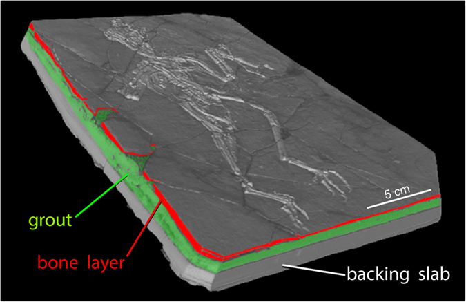
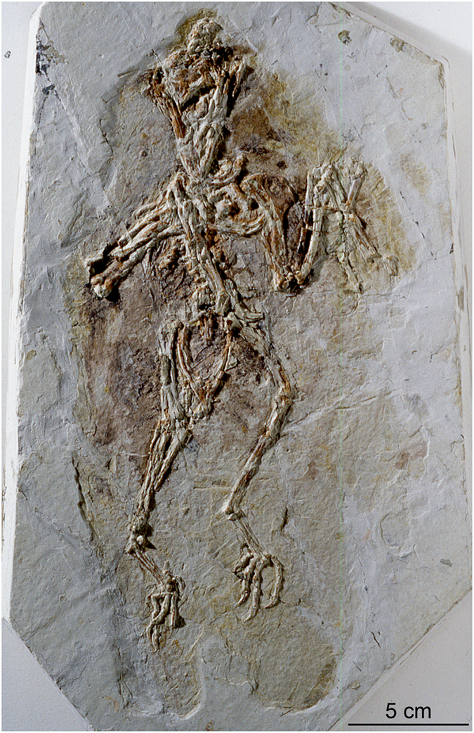
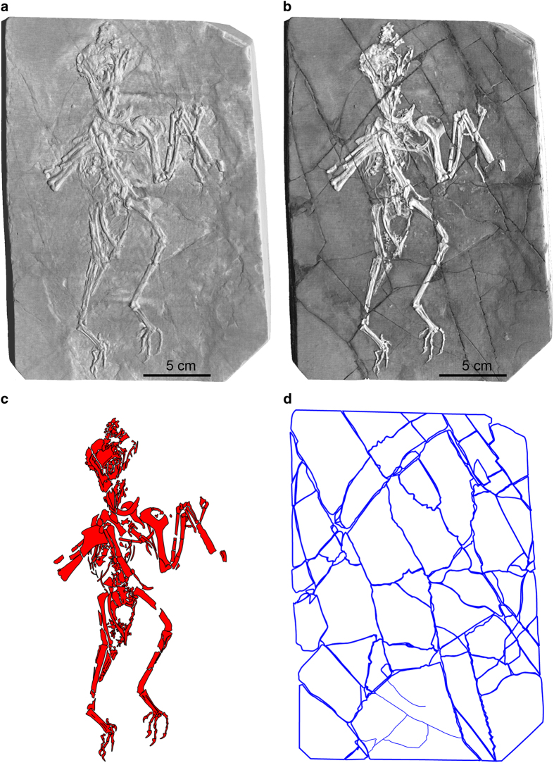
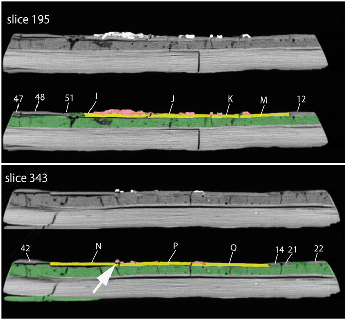
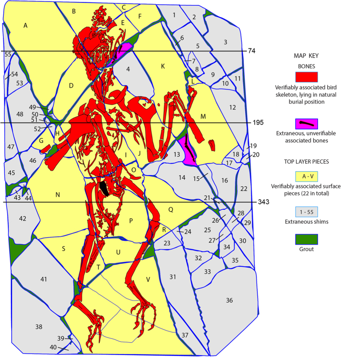
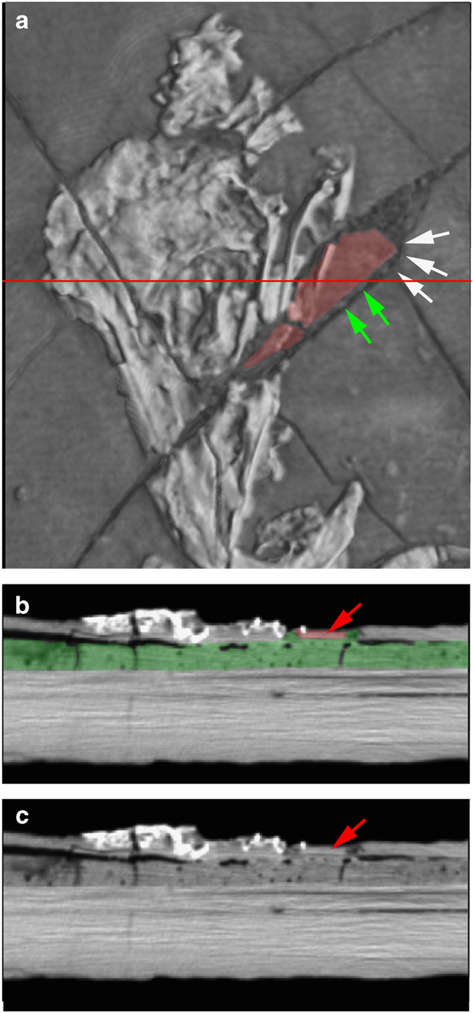
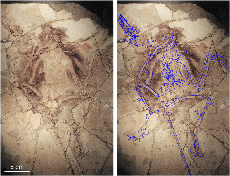
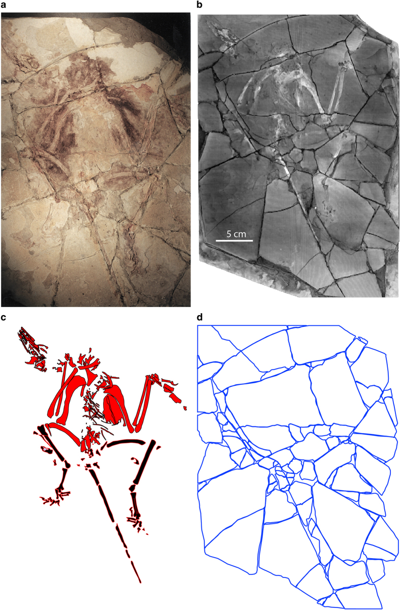
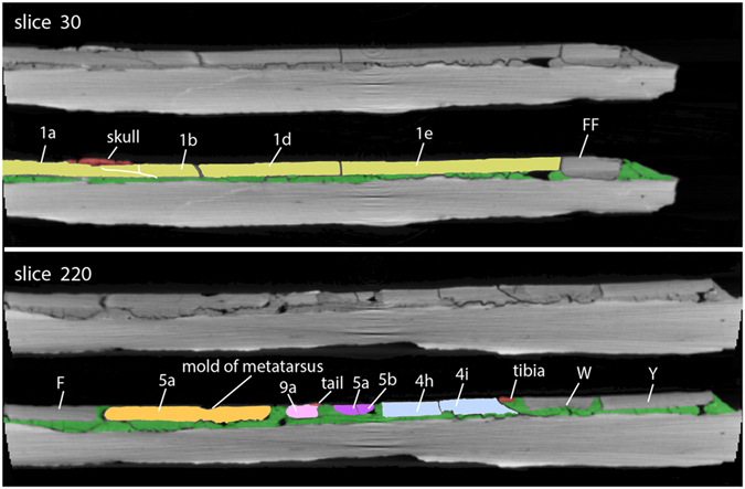
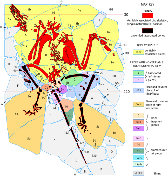
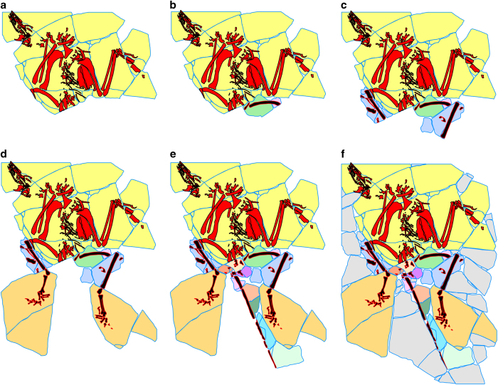
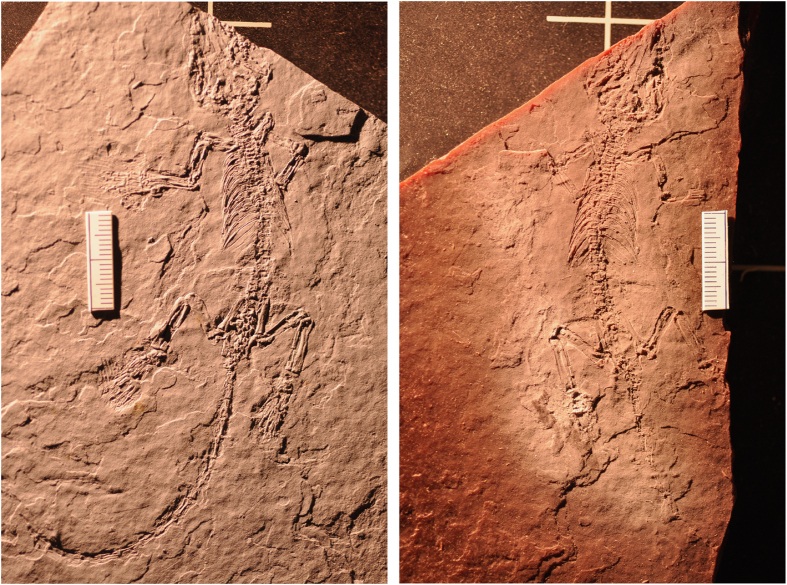
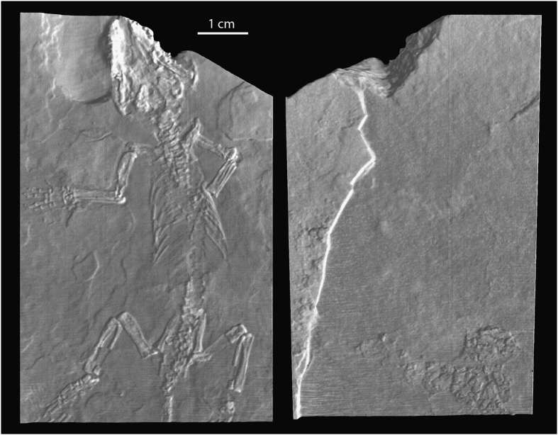
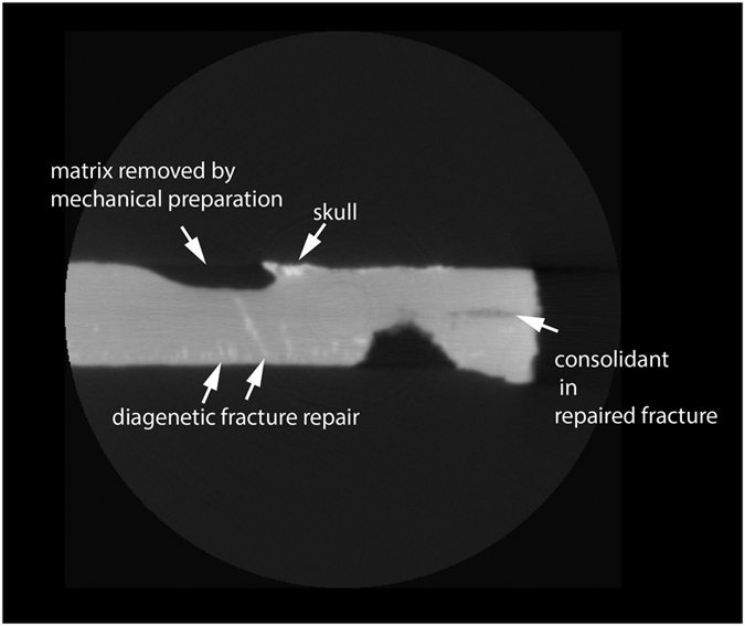
We describe X-ray computed tomography (CT) datasets from three specimens recovered from Early Cretaceous lakebeds of China that illustrate the forensic interpretation of CT imagery for paleontology. Fossil vertebrates from thinly bedded sediments often shatter upon discovery and are commonly repaired as amalgamated mosaics grouted to a solid backing slab of rock or plaster. Such methods are prone to inadvertent error and willful forgery, and once required potentially destructive methods to identify mistakes in reconstruction. CT is an efficient, nondestructive alternative that can disclose many clues about how a specimen was handled and repaired. These annotated datasets illustrate the power of CT in documenting specimen integrity and are intended as a reference in applying CT more broadly to evaluating the authenticity of comparable fossils.


Conflict of interest statement

The authors declare no competing financial interests.

Figures

Figure 1
Figure 1. The Confuciusornis amalgamation, in oblique view.
Volumetric rendering from CT data (Data Citation 1) showing its 3-layer man-made stratigraphy. The top layer is only 2–8 mm thick and was shattered during excavation. It was mosaicked together using a ceramic grout on a backing slab that provided structural integrity. Edges of the top bone-bearing layer are colored red; the middle layer consisting of grout is green; and the backing slab is gray.
Figure 2
Figure 2. Photograph of the Confuciusornis amalgamation as it was presented for CT scanning in 1998, taken with 35 mm color slide film (Photography by Joe Jaworowski).
Figure 3
Figure 3. A 3-D surface model of the Confuciusornis amalgamation (a), compared to a 3-D volumetric rendering (b) that shows more vividly its extensive fracture pattern.
Both were generated from the same high-resolution X-ray CT dataset (Data Citation 1). The skeleton (c) was digitally filtered from the rest of the amalgamation. The shatter-fracture pattern of the bone-bearing top layer (d) was mapped from the volumetric rendering and from cross-sections.
Figure 4
Figure 4. Confuciusornis amalgamation, showing slices 195 and 343 (see Fig. 5 for slice locations) in original gray scale (above), and color coded (below).
Contrast was adjusted and colors were added in Adobe Photoshop. Letters refer to the validated bone-bearing pieces and numbers refer to shims labeled in Fig. 5. In slice 343, the arrow points to a thin, black separation between a shard of the right femur (red) and the rest of the slab (yellow) filled with a low density consolidant, indicating that this piece was glued back onto the slab.
Figure 5
Figure 5. Map of the Confuciusornis amalgamation derived from high-resolution X-ray CT data (Data Citation 1).
The skeleton is in red and its associated shale is yellow. Extraneous bone-bearing pieces are magenta, construction shims are gray, and grout is green. The numbered lines indicate the positions of slice planes for original CT data labeled in Figs 4 and 6.
Figure 6
Figure 6. 3-D volume rendering of the Confuciusornis skull, showing two mismatched admixed fragments in map view (a).
The horizontal red line indicates the position of slice 74, which is shown as a colored cross section (b), and cross section without color (c). Color was added in Adobe Photoshop, to highlight the mismatched pieces. White arrows (a) indicate a mismatched rounded edge against which the squared corner of the extraneous red piece was fitted. Green arrows indicate ‘strings’ of grout used to hold the extraneous piece in place. Red arrows (b,c) point to the extraneous piece in cross section; note how thin it is compared to the pieces on either side, and that it is separated from adjacent bones by grout.
Figure 7
Figure 7. Photograph of the ‘Archaeoraptor’ amalgamation taken as it was presented for CT scanning at UTCT in August, 1999.
A series of professional large-format photographs taken in visible and ultraviolet light is available for viewing at http://digimorph.org/specimens/Archaeoraptor_forgery/.
Figure 8
Figure 8. ‘Archaeoraptor’ amalgamation.
Photo (a), volumetric reconstruction (b), silhouette of skeleton (red) and associated bones (black) (c), and fracture map of the top bone-bearing layer (d) (Data Citation 1).
Figure 9
Figure 9. ‘Archaeoraptor’ amalgamation, showing slices 30 and 220 in original grayscale (above), and color coded (below).
Contrast was increased and colors were added in Adobe Photoshop. Letters and numbers are keyed to Fig. 10.
Figure 10
Figure 10. Map of the ‘Archaeoraptor’ amalgamation, as it was presented for CT scanning at the University of Texas High-Resolution X-ray CT facility on July 29, 1999, with a key to its various parts.
The numbered lines indicate slice planes for original CT data labeled in Fig. 9.
Figure 11
Figure 11. The probable sequence of assembly of the top layer of the ‘Archaeoraptor’ amalgamation, starting with (a) the partial Yanornis skeleton, to which a split femur (b) was added, followed by the tibiae (c), the split (part and counter-part) foot (d), the tail (e), and finally the shims (f).
Figure 12
Figure 12. Photographs of part- and counter-part of Jeholodens jenkinsi as they were split upon discovery.
Only the main part (left) was CT scanned (Data Citation 1).
Figure 13
Figure 13. Volume rendering from CT data (Data Citation 1) of the Jeholodens specimen, showing the top (left) and bottom (right) of the main slab.
This small slab is virtually devoid of fractures.
Figure 14
Figure 14. Jeholodens.
Sample XY section (slice 59).

Comment on

  • Crystal structure of rhodopsin bound to arrestin by femtosecond X-ray laser.
    Kang Y, Zhou XE, Gao X, He Y, Liu W, Ishchenko A, Barty A, White TA, Yefanov O, Han GW, Xu Q, de Waal PW, Ke J, Tan MH, Zhang C, Moeller A, West GM, Pascal BD, Van Eps N, Caro LN, Vishnivetskiy SA, Lee RJ, Suino-Powell KM, Gu X, Pal K, Ma J, Zhi X, Boutet S, Williams GJ, Messerschmidt M, Gati C, Zatsepin NA, Wang D, James D, Basu S, Roy-Chowdhury S, Conrad CE, Coe J, Liu H, Lisova S, Kupitz C, Grotjohann I, Fromme R, Jiang Y, Tan M, Yang H, Li J, Wang M, Zheng Z, Li D, Howe N, Zhao Y, Standfuss J, Diederichs K, Dong Y, Potter CS, Carragher B, Caffrey M, Jiang H, Chapman HN, Spence JC, Fromme P, Weierstall U, Ernst OP, Katritch V, Gurevich VV, Griffin PR, Hubbell WL, Stevens RC, Cherezov V, Melcher K, Xu HE. Kang Y, et al. Nature. 2015 Jul 30;523(7562):561-7. doi: 10.1038/nature14656. Epub 2015 Jul 22. Nature. 2015. PMID: 26200343 Free PMC article.
  • The trickle before the torrent-diffraction data from X-ray lasers.
    Maia FR, Hajdu J. Maia FR, et al. Sci Data. 2016 Aug 1;3:160059. doi: 10.1038/sdata.2016.59. Sci Data. 2016. PMID: 27479637 Free PMC article.

References

Data Citations

    1. Rowe T., Luo Z., Ketcham R. A., Maisano J. A., Colbert M. W. 2016. Figshare. http://dx.doi.org/10.6084/m9.figshare.c.1612235 - DOI

References

    1. Charlesworth E. Hawkins’ sale to the British Museum and his criminal libel case against Charlesworth. Ann. Mag. Nat. Hist. new series 4, 11–44 (1840).
    1. Wellnhofer P. Campylognathoides liasicus (Quenstedt), an upper Liassic pterosaur from Holzmaden—the Pittsburgh specimen. Ann. Carnegie Mus. 45, 5–34 (1974).
    1. McGowen C. Problematic ichthyosaurs from southwest England: a question of authenticity. J. Vert. Paleontol. 10, 72–79 (1990).
    1. Sereno P. & Wild R. Procompsognathus: theropod, ‘thecodont’ or both? J. Vert. Paleontol. 12, 435–458 (1992).
    1. Stokstad E. Learning to dissect dinosaurs—digitally. Science 288, 1728–1732 (2000). - PubMed

Publication types