Review
. 2016 Aug;17(8):465-79.
doi: 10.1038/nrm.2016.65. Epub 2016 Jun 15.

Chaperoning SNARE assembly and disassembly

Affiliations
Review

Chaperoning SNARE assembly and disassembly

Richard W Baker et al. Nat Rev Mol Cell Biol. 2016 Aug.

Abstract

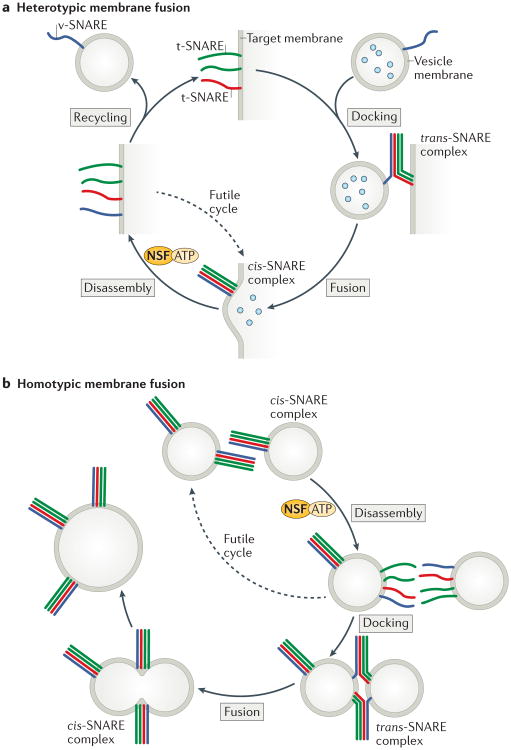
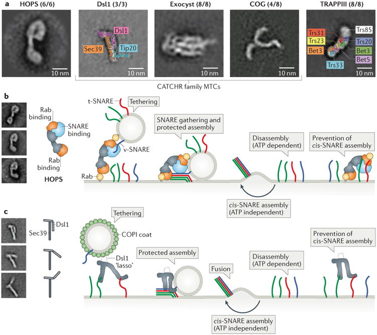
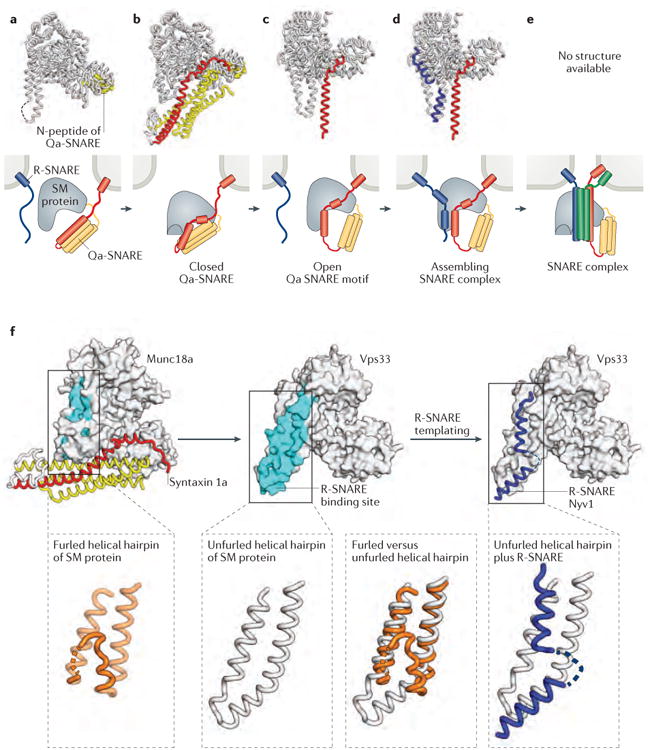
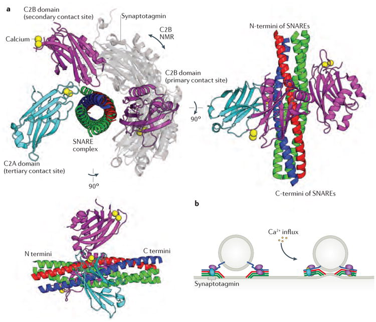
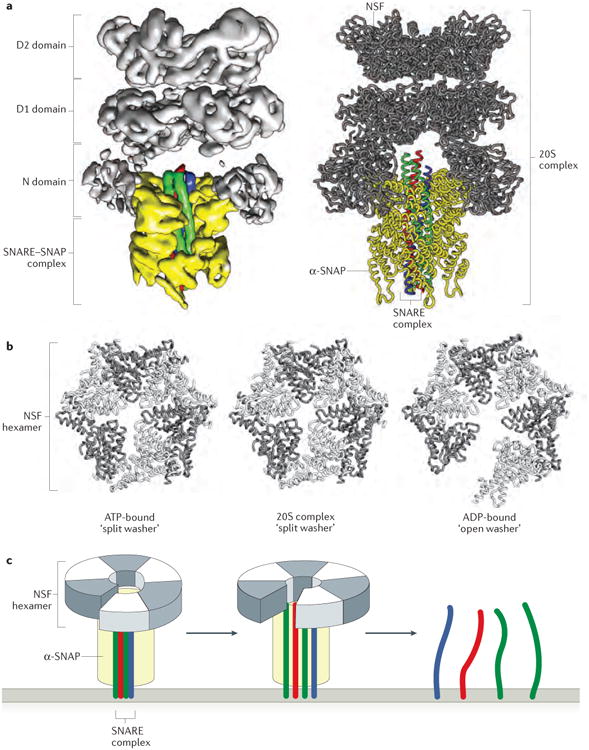
Intracellular membrane fusion is mediated in most cases by membrane-bridging complexes of soluble N-ethylmaleimide-sensitive factor attachment protein receptors (SNAREs). However, the assembly of such complexes in vitro is inefficient, and their uncatalysed disassembly is undetectably slow. Here, we focus on the cellular machinery that orchestrates assembly and disassembly of SNARE complexes, thereby regulating processes ranging from vesicle trafficking to organelle fusion to neurotransmitter release. Rapid progress is being made on many fronts, including the development of more realistic cell-free reconstitutions, the application of single-molecule biophysics, and the elucidation of X-ray and high-resolution electron microscopy structures of the SNARE assembly and disassembly machineries 'in action'.


Figures

Figure 1
Figure 1. Cycles of SNARE assembly and disassembly
a | Heterotypic membrane fusion is thought to begin with a v-SNARE in a vesicle and three t-SNAREs in a target membrane. Assembly into membrane-bridging trans-SNARE complexes drives membrane fusion and cargo delivery. The resulting cis-SNARE complex is disassembled by the ATPase NSF (working together with the adaptor protein SNAP; not shown), which releases the SNAREs for subsequent cycles of assembly and disassembly. If reassembly of the SNARE complex occurs before the v-SNARE is removed for recycling back to its donor (vesicle) compartment, the resulting cis-SNARE complex must be disassembled without having catalyzed membrane fusion (a futile cycle). b | In homotypic membrane fusion, each of the two membranes contains all four SNAREs. The resulting cis-SNARE complexes on each membrane must be disassembled prior to trans-SNARE complex assembly and membrane fusion. As in the case of heterotypic fusion, this cycle must operate in the continual presence of NSF and SNAP. To avoid futile cycling, chaperones are required to privilege trans-SNARE complex assembly over cis-SNARE complex assembly.
Figure 2
Figure 2. Membrane tethering and SNARE assembly
a | Membrane tethering factors include coiled-coil homodimers (not shown) and multisubunit tethering complexes (MTCs). Shown for the MTCs are representative class averages, derived from negative-stain electron micrographs, for the HOPS, Dsl1 (Dsl1 and Sec39 subunits only), exocyst, COG (Cog1-4 subunits only) and TRAPPIII complexes, as well as x-ray structure-based models for Dsl1 and TRAPPI complexes. The numbers in parentheses indicate the number of subunits imaged (present/total) by electron microscopy (or, in the case of Dsl1, by x-ray crystallography). Class averages reproduced with permission from REFS. 63, , , and . b | Simplified model for HOPS complex-dependent membrane tethering and fusion. In this model, HOPS functions first as a tether, by binding to Rab proteins on two different membranes, and then as a chaperone for SNARE complex assembly. HOPS may also block the premature disassembly of trans-SNARE complexes and the futile reassembly of cis-SNARE complexes. The structure of the HOPS complex is based on negative-stain electron microscopy. For clarity, the soluble Qc-SNARE Vam7 is shown with a membrane anchor. Electron microscopy-based class averages reproduced with permission from REF. 63. c | Model for Dsl1 complex-dependent membrane tethering and fusion. In this model, the Dsl1 complex mediates tethering by binding to SNARE proteins on the target membrane and — via an unstructured ‘lasso’ within the Dsl1 subunit — to the COPI coat on cargo-carrying vesicles. Next, the Dsl1 complex chaperones the proper assembly of trans-SNARE complexes. A hinge region within the Dsl1 subunit of the complex is evident in class averages of Dsl1–Sec39 complexes (reproduced with permission from REF. 71).
Figure 3
Figure 3. A structure-based mechanism for SM protein-mediated SNARE complex assembly
a-e | X-ray crystal structures (first row) and schematic representations (second row) of SM protein–SNARE complexes. The structures and schematics are placed in a speculative order to suggest a potential pathway for SM protein-templated SNARE complex assembly. a | Many SM proteins bind to the N-peptide lying at the extreme N-terminus of Qa- (or syntaxin-like) SNAREs. Shown is the structure of the SM protein Munc18a (grey) bound to the N-peptide of syntaxin 4 (yellow) (PDB code 3PUJ). b | Some Qa-SNAREs adopt an auto-inhibited conformation that binds to, and is stabilized by, the cognate SM protein. This binding mode requires a furled conformation for the helical hairpin of the SM protein. Shown is the structure of Munc18a bound to the cytoplasmic portion of syntaxin 1a (yellow and red) (PDB code 3C98). c | The opening of the Qa-SNARE is accompanied by the unfurling of the SM protein's helical hairpin, which exposes the R-SNARE binding site. Shown is the structure of the SM protein Vps33 (grey) bound to the SNARE motif of the Qa-SNARE Vam3 (red) (PDB code 5BUZ). d | Binding of the R-SNARE to the SM protein leads to a half-zippered SNARE complex representing a potential early intermediate in SNARE complex assembly. Shown is a model that combines the structures of Vps33 bound to the R-SNARE Nyv1 (blue) (PDB code 5BV0) and Vp33 bound to the Qa-SNARE Vam3 (red and yellow) (PDB code 5BUZ). e | After formation of the trans-SNARE complex, SM proteins may bind directly to the resulting four-helix bundle. The resulting complex has not, however, been structurally defined. f | Unfurling of the domain 3a helical hairpin of the SM protein reveals the R-SNARE binding site.
Figure 4
Figure 4. Structural characterization of the synaptotagmin–SNARE complex interaction
a | Superimposed structures of synaptotagmin 1 bound to the neuronal SNARE complex, determined by x-ray crystallography (PDB code 5CCH) and NMR (PDB code 2N1T), implicate the same face of the SNARE complex as being the primary contact site for the C2B domain of synaptotagmin (shown in purple for the crystal structure and in grey for the NMR structure). The x-ray crystal structure also defines secondary and tertiary binding sites on the SNARE complex for the C2A (cyan) and C2B domains of synaptotagmin. b | The structural data suggest a model in which multiple synaptotagmins and SNARE complexes form a super-complex around a docked vesicle. Calcium influx is proposed to promote interactions between synaptotagmin 1 and the plasma membrane that deform the plasma membrane, bringing it into juxtaposition with the vesicle membrane and facilitating membrane fusion.
Figure 5
Figure 5. SNARE complex disassembly by NSF and SNAPs
a | The near atomic-resolution cryoEM structure of the 20S complex comprising six copies of NSF, four copies of α-SNAP and the neuronal SNARE complex (PDB code 3J96). A ribbon model of the complex is shown next to the electron density from one of four single particle reconstructions. b | The D1 domains of the NSF hexamer are shown for three separate structures of NSF: the 20S complex, ATP-bound NSF (PDB code 3J94) and ADP-bound NSF (PDB code 3J95) (lacking α-SNAP and the SNARE complex). Comparison of these structures shows that NSF adopts a split washer orientation when bound to ATP and within the 20S complex, and an open washer orientation when bound to ADP. c | A simplified schematic of NSF and its interaction with the SNARE complex (only the D1 domain of NSF is shown for clarity). When bound to ATP and the SNARE complex, NSF adopts a compact, split-washer orientation. Upon ATP hydrolysis and release of inorganic phosphate, NSF undergoes a conformational change to the open-washer orientation, thereby applying rotational and shear forces to the SNARE complex. This spring-like transition unwinds the SNARE complex in a single round of ATP hydrolysis, which releases the individual SNAREs for participation in further rounds of membrane fusion,.

References

    1. Südhof TC, Rothman JE. Membrane fusion: grappling with SNARE and SM proteins. Science. 2009;323:474–477. - PMC - PubMed
    1. Jahn R, Scheller RH. SNAREs--engines for membrane fusion. Nat Rev Mol Cell Biol. 2006;7:631–643. - PubMed
    1. Fasshauer D, Sutton RB, Brunger AT, Jahn R. Conserved structural features of the synaptic fusion complex: SNARE proteins reclassified as Q- and R-SNAREs. Proc Natl Acad Sci U S A. 1998;95:15781–15786. - PMC - PubMed
    1. Stein A, Weber G, Wahl MC, Jahn R. Helical extension of the neuronal SNARE complex into the membrane. Nature. 2009;460:525–528. - PMC - PubMed
    1. Sutton RB, Fasshauer D, Jahn R, Brunger AT. Crystal structure of a SNARE complex involved in synaptic exocytosis at 2.4 angstrom resolution. Nature. 1998;395:347–353. - PubMed

LinkOut - more resources