Comparative Study
. 2016 Jun;9(6):10.1161/CIRCEP.115.003841 e003841.
doi: 10.1161/CIRCEP.115.003841.

High-Resolution Mapping of Ventricular Scar: Comparison Between Single and Multielectrode Catheters

Affiliations
Comparative Study

High-Resolution Mapping of Ventricular Scar: Comparison Between Single and Multielectrode Catheters

Cory M Tschabrunn et al. Circ Arrhythm Electrophysiol. 2016 Jun.

Abstract

Background: Mapping resolution is influenced by electrode size and interelectrode spacing. The aims of this study were to establish normal electrogram criteria for 1-mm multielectrode-mapping catheters (Pentaray) in the ventricle and to compare its mapping resolution within scar to standard 3.5-mm catheters (Smart-Touch Thermocool).

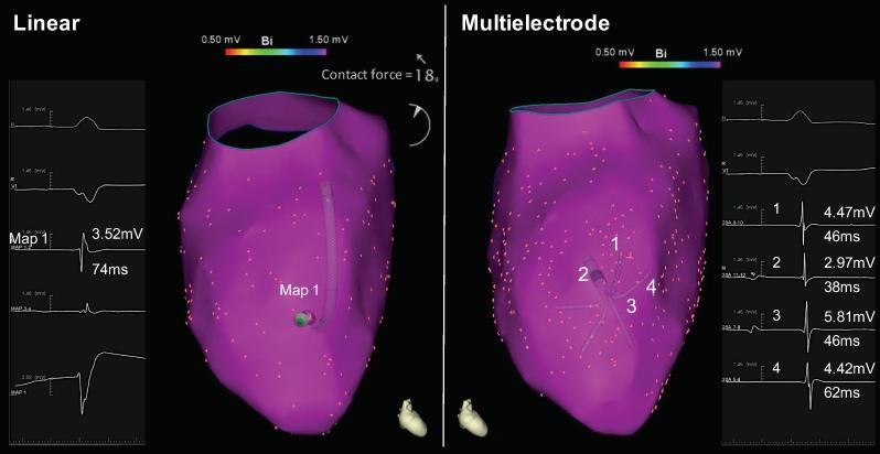
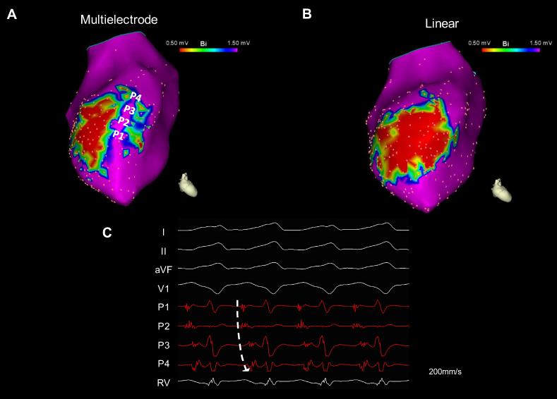
Methods and results: Three healthy swine and 11 swine with healed myocardial infarction underwent sequential mapping of the left ventricle with both catheters. Bipolar voltage amplitude in healthy tissue was similar between 3.5- and 1-mm multielectrode catheters with a 5th percentile of 1.61 and 1.48 mV, respectively. In swine with healed infarction, the total area of low bipolar voltage amplitude (defined as <1.5 mV) was 22.5% smaller using 1-mm multielectrode catheters (21.7 versus 28.0 cm2; P=0.003). This was more evident in the area of dense scar (bipolar amplitude <0.5 mV) with a 47% smaller very low-voltage area identified using 1-mm electrode catheters (7.1 versus 15.2 cm(2); P=0.003). In this region, 1-mm multielectrode catheters recorded higher voltage amplitude (0.72±0.81 mV versus 0.30±0.12 mV; P<0.001). Importantly, 27% of these dense scar electrograms showed distinct triphasic electrograms when mapped using a 1-mm multielectrode catheter compared with fractionated multicomponent electrogram recorded with the 3.5-mm electrode catheter. In 8 mapped reentrant ventricular tachycardias, the circuits included regions of preserved myocardial tissue channels identified with 1-mm multielectrode catheters but not 3.5-mm electrode catheters. Pacing threshold within the area of low voltage was lower with 1-mm electrode catheters (0.9±1.3 mV versus 3.8±3.7 mV; P=0.001).

Conclusions: Mapping with small closely spaced electrode catheters can improve mapping resolution within areas of low voltage.

Keywords: electrodes; heart; myocardial infarction; swine; ventricular tachycardia.


Figures

Figure 1
Figure 1
Differences between a standard 3.5mm distal electrode catheter (Thermocool®; “linear”) and a 1mm multielectrode mapping catheter (Pentaray®; “multielectrode”). Panel A: The linear ablation catheter has a 3.5mm distal electrode that is separated by 1.0mm from a 2.0mm proximal electrode, resulting in a center-to-center distance of 3.75mm. Panel B: The multielectrode-mapping catheter has 1.0mm electrodes that are separated by 2.0mm, resulting in a center-to-center distance of 3.0mm (photographs adapted with permission from Biosense Webster, Inc). Panel C: Schematic illustration of a linear and a multielectrode mapping catheters placed within a zone of heterogeneous scar that contains collagen (grey dotted rectangle) and a surviving myocardial bundle (white line). When the linear catheter is placed over a small surviving myocardial bundle that is significantly smaller than the recording electrode, the electrogram contains data from both the surviving myocardial bundle and the surrounding scar tissue, resulting in a low amplitude, long-duration and fractionated electrogram (electrogram on left). However, when the multielectrode mapping catheter with its much smaller electrode is placed over the surviving myocardial bundle, the recorded electrogram contains data largely representing the surviving myocardial bundle, thus resulting in high amplitude narrow electrogram (electrogram on right).
Figure 2
Figure 2
Electroanatomical mapping (EAM) of healthy ventricular tissue: comparison between linear and multielectrode catheters. The left panel shows EAM map of a normal left ventricle (LV) using a linear catheter (Smart-Touch Thermocool®) while the right panel shows EAM of the same LV performed immediately afterward using a multielectrode mapping catheter (Pentaray®). The maps are showed in an anterior-posterior projection and with a bipolar voltage range of 0.5-1.5mV. The bipolar voltage amplitude was similar between the two maps with 95% of all electrograms >1.5mV. However, electrogram duration was shorter using the multielectrode-mapping catheter. The shorter electrogram duration is due to the smaller interelectrode spacing that results in shorter conduction time between the proximal and distal electrodes.
Figure 3
Figure 3
Comparison of bipolar voltage amplitude between linear and multielectrode mapping catheters in the post-infarct zone. Panel A: Bipolar voltage amplitude distribution within the low voltage area defined as ≤1.5mV using the linear catheter. Mapping with multielectrode catheters recorded a significantly higher voltage at a similar catheter position (p<0.001). Panel B: Comparison of bipolar voltage within the area of very low voltage (“dense scar”) defined as ≤0.5mV using the linear catheter. The multielectrode catheter recorded a significantly higher bipolar voltage amplitude at a similar catheter position (p<0.001).
Figure 4
Figure 4
Electroanatomic maps (EAMs) of the left ventricle in 3 representative examples of post-infarction swine. For each example, the EAM made with the linear catheter is shown on the left while the EAM made with the multielectrode catheter is shown on the right. The maps are displayed in the anterior-posterior view and with a bipolar voltage range of 0.5 to 1.5mV. In 7 of 11 swine, the mapping resolution within the area of low voltage significantly diverged: while mapping with a linear catheter demonstrated homogenous and confluent low voltage area, mapping with a multielectrode catheter revealed areas “channels” of normal bipolar voltage amplitude and electrogram characteristics within the low voltage zone (Swine 1 and 2). In 4 of 11 swine, mapping with both catheters demonstrated a confluent area of low voltage that was similar between the catheters (Swine 3).
Figure 5
Figure 5
Relationship between late gadolinium enhancement (LGE) and bipolar voltage amplitude recorded with linear and multielectrode mapping catheters. Panel A shows LGE in the anterior septum extending from the left ventricle (LV) to the right ventricle (RV). The arrows are pointed to an area of preserved subendocardial myocardium. The multielectrode mapping catheter with its small and closely-spaced multielectrodes was largely influenced by the closer layer of surviving subendocardial myocardium and recorded a normal or near normal bipolar voltage amplitude (+++). In contrast, the linear catheter with its larger electrodes and longer interelectrode spacing recorded data representative of a larger field of view containing the thin layer of surviving subendocardial tissue, however this was overwhelmed by the thicker layer of scar, thus resulting in a low bipolar voltage (+). Panel B shows an example of limited subepicardial (right ventricular) scar with normal LV sub and midmyocardial tissue. In these cases, both catheters recorded a normal or nearly normal bipolar voltage amplitude (+++).
Figure 6
Figure 6
Relationship between histology and bipolar voltage amplitude recorded with linear and multielectrode mapping catheters. The left panel shows a section of an infarcted anterior left ventricular wall made perpendicular to the fiber direction, displaying the tissue from its endocardial to epicardial layer. The left panel shows a narrow layer of subendocardial surviving muscle with a deeper layer of collagen (blue stain). In these areas, the multielectrode mapping catheter recorded normal or nearly normal bipolar voltage amplitude (+++) while the linear catheter recorded low bipolar voltage amplitude (+). The right panel shows a section of transmural infarction without surviving myocardium (the subendocardial layer in red are red blood cells). In these areas both catheters recorded low bipolar voltage amplitude (+). Histologic preparation with mason-trichrome staining (5x).
Figure 7
Figure 7
Identification of a ventricular tachycardia (VT) isthmus by multielectrode mapping catheters. In this example, a channel of healthy subendocardial tissue vertically transecting the anterior wall scar was identified during sinus rhythm with a multielectrode mapping catheter (Panel A) but not with a linear catheter (Panel B). Electrograms recorded during sinus rhythm at the channel were triphasic, narrow, and with a bipolar voltage amplitude >1.5mV. During VT, the multielectrode catheter was positioned within the channel and recorded diastolic electrical activity with a wave front propagating superiorly, consistent with a basal exit (Panel C). Ablation at the site of P1 electrode resulted in rapid termination of the VT.
Figure 8
Figure 8
Difference in electrogram amplitude between multielectrode and linear catheters. The linear and multielectrode catheters were both placed at a site with diastolic electrical activity during ventricular tachycardia (VT). While the multielectrode catheter recorded narrow electrograms with near-normal bipolar voltage amplitude (0.62-1.42mV), the linear catheter, placed at similar position and with a tissue contact force of 15gr recorded a fractionated very low amplitude signal (0.08mV).

Comment in

References

    1. Fenoglio JJ, Jr., Pham TD, Harken AH, Horowitz LN, Josephson ME, Wit AL. Recurrent sustained ventricular tachycardia: structure and ultrastructure of subendocardial regions in which tachycardia originates. Circulation. 1983;68:518–533. - PubMed
    1. de Bakker JM, van Capelle FJ, Janse MJ, Wilde AA, Coronel R, Becker AE, Dingemans KP, van Hemel NM, Hauer RN. Reentry as a cause of ventricular tachycardia in patients with chronic ischemic heart disease: electrophysiologic and anatomic correlation. Circulation. 1988;77:589–606. - PubMed
    1. Anter E, Tschabrunn CM, Buxton AEJM. Characteristics of Reentrant Ventricular Tachycardia in Healed Myocardial Infarction. Heart Rhythm. 2015;12:S204.
    1. Tschabrunn CM, Roujol S, Nezafat R, Faulkner-Jones B, Buxton AE, Josephson ME, Anter E. A swine model of infarct-related reentrant ventricular tachycardia: Electroanatomic, magnetic resonance, and histopathological characterization. Heart Rhythm. 2016;13:262–273. - PMC - PubMed
    1. Akçakaya M, Rayatzadeh H, Basha TA, Hong SN, Chan RH, Kissinger KV, Hauser TH, Josephson ME, Manning WJ, Nezafat R. Accelerated late gadolinium enhancement cardiac MR imaging with isotropic spatial resolution using compressed sensing: initial experience. Radiology. 2012;264:691–699. - PMC - PubMed

Publication types

MeSH terms