. 2016 Jun 22:7:11984.
doi: 10.1038/ncomms11984.

The role of MscL amphipathic N terminus indicates a blueprint for bilayer-mediated gating of mechanosensitive channels

Affiliations

The role of MscL amphipathic N terminus indicates a blueprint for bilayer-mediated gating of mechanosensitive channels

Navid Bavi et al. Nat Commun. .

Abstract

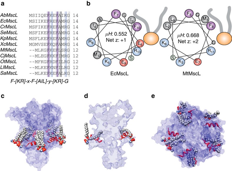
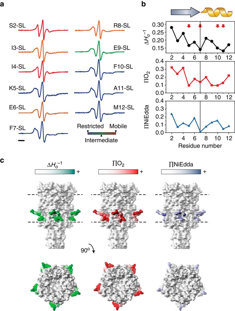
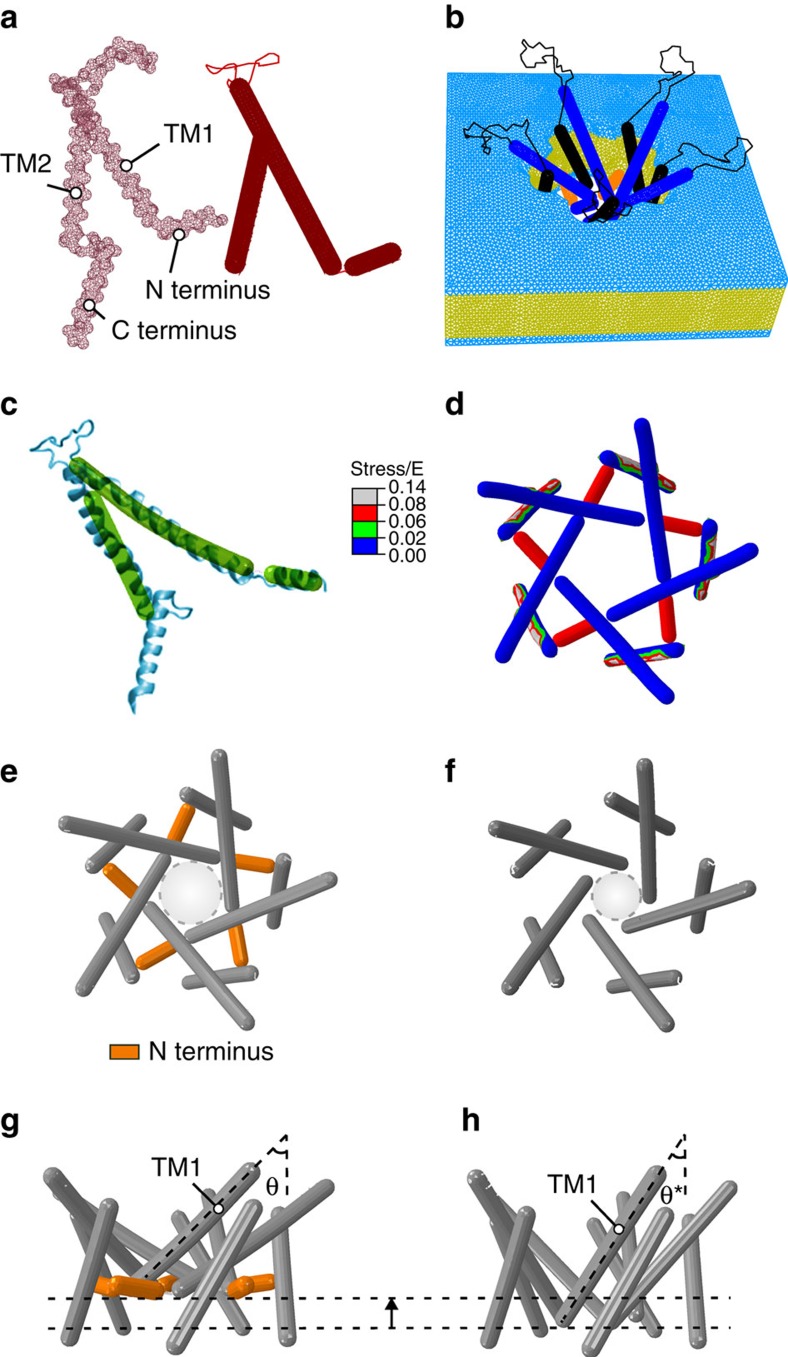
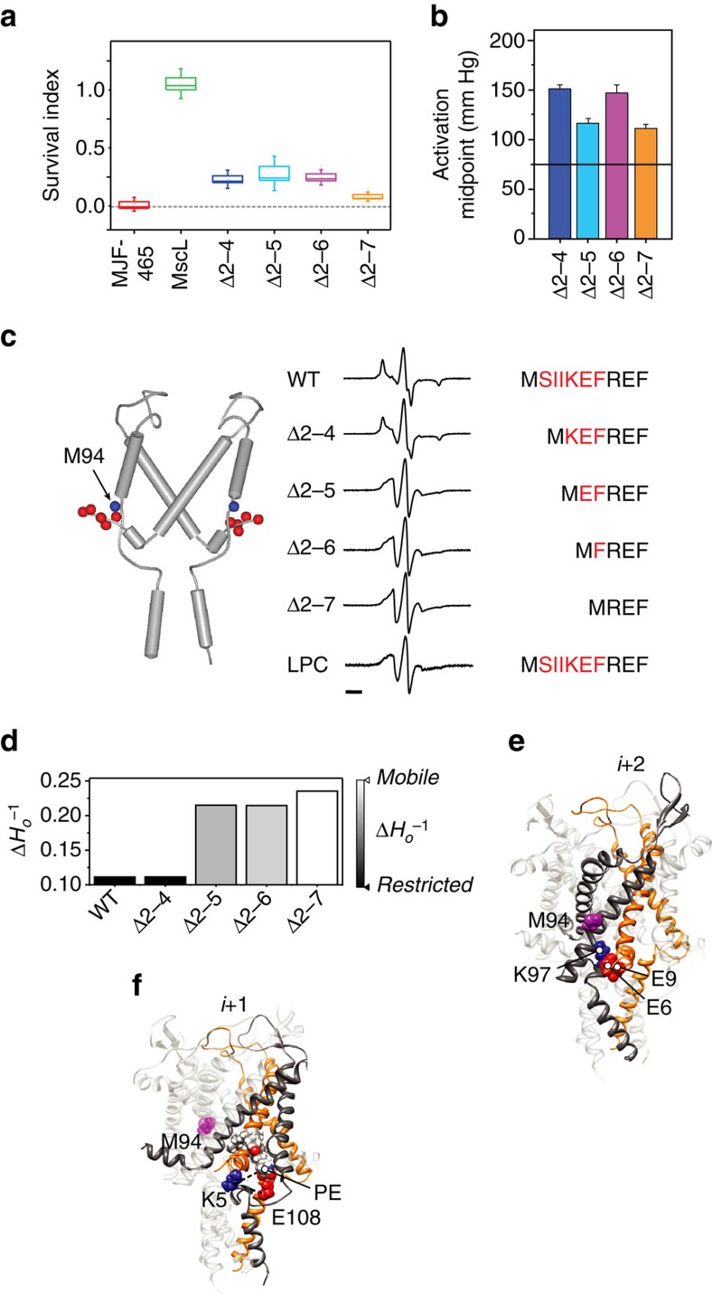
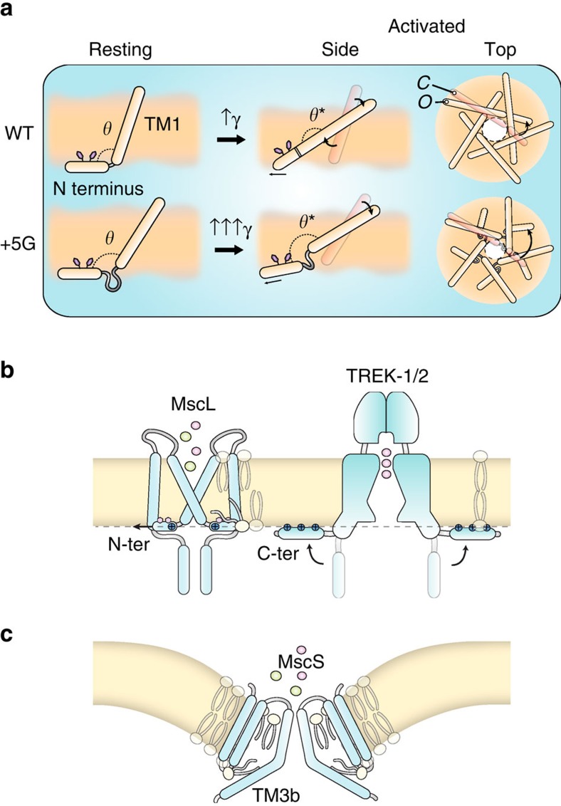
The bacterial mechanosensitive channel MscL gates in response to membrane tension as a result of mechanical force transmitted directly to the channel from the lipid bilayer. MscL represents an excellent model system to study the basic biophysical principles of mechanosensory transduction. However, understanding of the essential structural components that transduce bilayer tension into channel gating remains incomplete. Here using multiple experimental and computational approaches, we demonstrate that the amphipathic N-terminal helix of MscL acts as a crucial structural element during tension-induced gating, both stabilizing the closed state and coupling the channel to the membrane. We propose that this may also represent a common principle in the gating cycle of unrelated mechanosensitive ion channels, allowing the coupling of channel conformation to membrane dynamics.


Figures

Figure 1
Figure 1. Conservation and amphipathic nature of the N-terminal helix in bacterial homologues of MscL.
(a) Sequence alignment of MscL homologues from different bacterial classes with the consensus sequence shown below. (b) Helical wheel diagrams showing the amphipathic nature of the N-terminal helix of both E. coli (EcMscL) and M. tuberculosis (MtMscL) MscL. Amphipathic helices classically have high hydrophobic moments (>0.45 μH). (c,d) This type of helix with a high hydrophobic moment usually interacts at the interfacial region of a lipid bilayer with the hydrophobic face buried. Here the orientation of the N-terminal helix parallel to the membrane plane is shown from an equilibrated MD simulation model of EcMscL (see Fig. 4). Here we can also clearly see how the acyl chains bend over the N-terminal helix and protrude into an inter-subunit cavity. (e) Top view of the N-terminal helix showing its orientation and membrane association.
Figure 2
Figure 2. Site-directed spin-labelling analysis of the MscL N terminus.
(a) X-band CW-EPR spectra of spin-labelled N-terminal mutants reconstituted into azolectin liposomes. Spectra are colour-coded according to their overall probe dynamics as shown in the colour gradient (bottom right). (b) Environmental parameter profiles derived from the spectra in a or from power saturation experiments. Mobility parameter ΔHo−1 (top panel, black circles), oxygen-accessibility parameter ΔO2 (centre panel, red squares) and NiEdda-accessibility parameter ΔNiEdda (bottom panel, blue triangles). A cartoon of the assigned secondary structure for this segment is shown on top. Bar represents 20 G. (c) EPR-derived structural data mapped on MtMscL. The side and top (extracellular) views of the mapped EPR data are displayed on solvent-accessible surfaces calculated in UCSF Chimera with a probe radius of 1.4 Å. Green tones, probe mobility (ΔHo−1). Red tones, oxygen-accessibility parameter (ΔO2). Blue tones, NiEdda-accessibility parameter (ΔNiEdda). The dotted parallel lines represent the putative location of the lipid bilayer.
Figure 3
Figure 3. The crucial role of the N-terminal domain in the gating of MscL shown by a parametric FE simulation.
(a) Mesh representation of a subunit of WT EcMscL obtained from an EcMscL homology model based on MtMscL (PDB: 2OAR; left panel—red mesh) and the FE model of a subunit of EcMscL without the C-terminal domain (right panel—solid red rods). The α-helices are modelled as elastic rods and the loops are modelled as nonlinear springs. (b) The FE structure of EcMscL is embedded into the lipid bilayer with the mesh distribution shown. (c) Superposition of FE EcMscL open structure with a previously obtained restrained MD simulation of EcMscL. (d) Effective (Von Mises) stress distribution in the open state (top view). The membrane tensional stress is made dimensionless using the Young's modulus of EcMscL, E, that is, stress/E. The nondimensional stress is 0.6. (e,f) Channel pore in an expanded state, with and without the N terminus (top view). The nondimensional exerted stress on the membrane is 0.3 in both models, and thus they do not represent fully open structures. The light grey dashed circles in e,f represent the position of the effective pore with respect to the plane of the membrane. This diameter is, however, not the actual pore size, since it does not show the side chains on each TM1. The effective pore diameter of the WT model is ∼24 Å, and the model that lacks the N terminus is ∼18 Å. (g) Side view of a WT subunit showing that the angle between the N-terminal domain and the TM1 helix increases as the channel begins to gate. Moreover, they both tilt upwards towards the membrane midplane as the membrane is stretched. (h) TM1 has less out-of-plane tilting in the absence of the N terminus (θ*=33°) compared with the WT channel (θ=45°). Overall, these results suggest that the N-terminal helices have a significant role in transferring the force from the lipid to the pore-lining TM1 helix, guiding both its tilting and expansion.
Figure 4
Figure 4. Probing the functional role of the N-terminal domain and the physical interaction between the N terminus and TM2 by deletion analysis.
(a) Survival of MJF465 (MscL MscS MscK) E. coli expressing different deletion constructs of MscL after downshock from LB supplemented with 500 mM NaCl to LB (∼1,000 mOsm). Data shown as box plots indicating the mean, 25 and 75 percentile (box) and ±s.d. (capped lines). (b) Midpoint of pressure activation of individual deletion constructs determined from multichannel patches (n=4, Δ2–7, n=3; mean±s.d.). The dotted horizontal line represents the mean value for WT MscL. (c) Local dynamics at the intracellular end of TM2 (spin-labelled at position M94) as a function of N-terminal deletions. Left, cartoon representation of subunits i and i+2 showing the position of the spin-labelling site (blue sphere) and the individual residues in the N terminus that were deleted (red spheres). Right, EPR spectra of M94-SL in a WT background, four different deletions (Δ2–4, Δ2–5, Δ2–6 and Δ2–7) and the WT background opened in the presence of LPCs. The N-terminal sequence of MscL is shown with the region of deleted residues in red. Bar represents 20 G. (d) Calculated mobility parameter at position M94-SL for the different spin-labelled constructs in a,c. (e) A cartoon representation of the electrostatic interaction of the Glu (E6 and E9) residues on subunits i with Lys (K97) residue of the second adjacent (i+2) subunit. (f) A cartoon representation of the electrostatic interaction of the Lys (K5) residue on subunits i with Glu (E108) residue of the adjacent (i+1) subunit and phosphate group of a POPE lipid molecule. The position of M94 has been indicated as a purple sphere with respect to these residues in e,f.
Figure 5
Figure 5. Conformational changes at the N terminus associated with the channel opening.
(a) X-band CW-EPR spectra of liposome-reconstituted spin-labelled N-terminal mutants in the presence (red traces) and in the absence (black traces) of 25 mol% LPC to stabilize the open conformation. Experimental conditions as described in Fig. 3. Bar represents 30 G. (b) Environmental parameter profiles of the N terminus in the open state, derived from the spectra in a or from power saturation experiments. Mobility parameter ΔHo−1 (top panel, black circles), oxygen-accessibility parameter ΔO2 (centre panel, red squares) and NiEdda-accessibility parameter ΔNiEdda (bottom panel, blue triangles). For comparison, data for the closed state (from Fig. 2) are shown on each panel as grey open symbols. The vertical dashed lines point to the periodic maxima of NiEdda-accessibility and O2-accessibility minima in the open state.
Figure 6
Figure 6. All-atom MD simulations of WT and +5G mutant EcMscL models.
(a) Side and top views of WT MscL and +5G MscL in their resting equilibrated states. The TM1 helices in the +5G are slightly more tilted than in the WT model mostly because of the higher degree of freedom of TM1 in the +5G model. (b) Side and top views of WT and +5G MscL after 268 ns of simulation (for force regimen see Methods). The pore of the WT model is much more expanded than in the +5G model. This is because of the significant role of the N terminus in tilting TM1 in the membrane plane and in expanding the pore by driving the movement of TM1 away from the central axis. This ability is diminished by extending the Gly linker between the N terminus and TM1. (c) A surface representation of WT and +5G models in the resting and expanded states from the top. This clearly shows the difference in the degree of expansion. (d) The side and top views of the expanded state of the +5G mutant MscL model. To reach this state, the simulation was run for longer than the WT simulation (additional 5 ns under the high membrane surface tension of 100 mN m−1). (e) Closed (solid red) and expanded (dashed black) pore of WT MscL. (f) Closed (solid red) and expanded (dashed black) pore of +5G MscL. Comparing e,f shows that the upper regions of the +5G model in the closed state are substantially more expanded compared with WT because of an increased tilt of TM1 helices.
Figure 7
Figure 7. Effect of extension of the Gly linker between the N terminus and TM1 on MscL activation threshold in liposomes.
MscS and MscL are co-reconstituted in 100% azolectin lipid. (ac) Current traces of MscS and MscL recorded at +5-mV pipette potential. Red arrowheads point to the first observed MscS and MscL opening, used to determine the MscL/MscS first opening threshold ratio (TR). Blue arrowheads point to the last observed MscS closure and MscL closure. The vertical dashed line illustrates the midpoint activation threshold of the respective channels. (d,e) The comparison between activation TR of WT with +2G and +5G mutant MscL mutants. It can clearly be observed that extension of the G linker increases the activation threshold of MscL by almost 100%. (data points represent mean±s.e.m. *P-value<0.01; one-way ANOVA). (f) Single-channel recordings from WT MscL (upper panel: 3.04±0.04 nS (n=5)) and +5G MscL (lower panel: 2.76±0.08 nS (n=5)) both recorded at +20-mV pipette potential and after application of negative pressure. The +5G mutant channel gates at substates for a large percentage of the time especially when compared with WT, a fact largely because of the greater conformational freedom of the TM1 helix. (g) Effect of polar substitutions at position G14 on single-channel activity of MscL. G14S gives almost WT-like activity, whereas deletion of G14 results in a channel that gates spontaneously at substates, giving rise to a ‘leaky' toxic phenotype when expressed in E. coli. For ΔG14, the record shows the change in voltage from 0 to 20 mV pipette potential (red line) and the corresponding spontaneous activity.
Figure 8
Figure 8. Crucial role of the N-terminal domain in the gating of MscL.
(a) The N-terminal domain interacts tightly with the lipid bilayer. It orients at the lipid–solvent interface on the cytoplasmic side and acts as an anchor in stabilizing the closed state of the channel. As the lipid bilayer is stretched, the N-terminal helix is stretched following the trajectory of its surrounding lipid molecules but never becomes completely buried. Then, force is transmitted via the Gly14 residue to the end of TM1, which causes the alignment of TM1 with the N-terminal domain and the formation of a contiguous helix. If we extend the Gly linker (+5 G), we observe that one of the main roles of the N terminus is in expanding the pore. These functions are largely diminished in the +5G model because of the fact that TM1 does not follow the trajectory of the N-terminal region. (b,c) Horizontal membrane-coupling helices seem to be a hallmark of mechanosensitive channels. These helices maybe buried as in the N terminus of MscL, TM3b of MscS and the S4–S5 linker of TRPV4 or adsorbed on the membrane surface as in the C terminus of TREK channels. Owing to the various types of lipids present in different organisms and the divergent ways in which these coupling helices can interact, there is little to no necessity for sequence conservation despite the fact that they play an almost identical role.

Comment in

References

    1. Hamill O. P. & Martinac B. Molecular basis of mechanotransduction in living cells. Physiol. Rev. 81, 685–740 (2001). - PubMed
    1. Sukharev S. & Sachs F. Molecular force transduction by ion channels: diversity and unifying principles. J. Cell Sci. 125, 3075–3083 (2012). - PMC - PubMed
    1. Haswell E. S., Phillips R. & Rees D. C. Mechanosensitive channels: what can they do and how do they do it? Structure 19, 1356–1369 (2011). - PMC - PubMed
    1. Ranade S. S., Syeda R. & Patapoutian A. Mechanically activated ion channels. Neuron 87, 1162–1179 (2015). - PMC - PubMed
    1. Phillips R., Ursell T., Wiggins P. & Sens P. Emerging roles for lipids in shaping membrane-protein function. Nature 459, 379–385 (2009). - PMC - PubMed

Publication types

LinkOut - more resources