. 2016 Aug 11;166(4):1028-1040.
doi: 10.1016/j.cell.2016.06.016. Epub 2016 Jul 7.

Ultra-High Resolution 3D Imaging of Whole Cells

Affiliations

Ultra-High Resolution 3D Imaging of Whole Cells

Fang Huang et al. Cell. .

Abstract

Fluorescence nanoscopy, or super-resolution microscopy, has become an important tool in cell biological research. However, because of its usually inferior resolution in the depth direction (50-80 nm) and rapidly deteriorating resolution in thick samples, its practical biological application has been effectively limited to two dimensions and thin samples. Here, we present the development of whole-cell 4Pi single-molecule switching nanoscopy (W-4PiSMSN), an optical nanoscope that allows imaging of three-dimensional (3D) structures at 10- to 20-nm resolution throughout entire mammalian cells. We demonstrate the wide applicability of W-4PiSMSN across diverse research fields by imaging complex molecular architectures ranging from bacteriophages to nuclear pores, cilia, and synaptonemal complexes in large 3D cellular volumes.


Figures

None
Graphical abstract
Figure 1
Figure 1
W-4PiSMSN Design and Resolution Demonstrations with ER, Microtubules, and Bacteriophages (A) Simplified optical diagram of W-4PiSMSN. (B) Overview and cross-sections of the ER network in an immunolabeled COS-7 cell. Cross-sections of the W-4PiSMSN reconstruction show clearly separated membranes of the tubular structures, which cannot be resolved with conventional astigmatism-based nanoscopy (light blue frame). (C) x-y slice through the mid-section of the ER network shown in (B) highlights the distinct membrane contour of ER tubules (arrowheads). (D) Overview of immunolabeled microtubules in a COS-7 cell. (E and F) 20-nm-thin x-y slices of the red (E) and green (F) segments shown in (D) demonstrate that microtubules can be easily resolved as hollow cylinders in W-4PiSMSN. (G) A look through a 120-nm-long segment of the microtubule of (F). (H) A histogram showing the number of localizations in a cross-section of the microtubule, white dotted box in (G). (I) A bacteriophage reconstructed from 115 averaged viral particles rendered in 3D. (J and K) 5-nm-thin vertical (J) and horizontal (K) slices through the averaged dataset corresponding to the planes shown in (I). (L) The internal angle measurements of the hexagon shape identified from the viral capsid shown in (J). OBJ, objective; QWP, quarter-wave plate; DM, dichroic mirror; QBF, quad-band band-pass filter; Def. Mirror, deformable mirror; Cam, camera; 50/50, beam splitter cube.
Figure 2
Figure 2
Two-Color Reconstruction of Mitochondria and Microtubules (A and B) W-4PiSMSN reconstruction of microtubules (A) and mitochondria (TOM20) (B) in a COS-7 cell immunolabeled with Alexa Fluor 647 and Cy3B, respectively. An x-y overview and x-z and y-z slices (yellow and magenta lines, respectively) are shown. (C) The combined two-color image reveals microtubules running adjacent to the mitochondria surface.
Figure 3
Figure 3
W-4PiSMSN Reconstruction of TOM20 on Mitochondria in COS-7 Cell (A) Overview of the mitochondria network visualized by immunolabeling TOM20 with Alexa Flour 647. The dataset is assembled from 11 optical sections with 500-nm step sizes. (B) x-z cross-section of the purple plane in (A) showing the distribution of TOM20 on the outer mitochondrial membrane. Ghost images are completely negligible. (C and D) Top (C) and side (D) views of the orange box in (A) show the 3D arrangement of the organelle.
Figure 4
Figure 4
W-4PiSMSN Imaging of Nuclear Pore Complexes over the Thickness of a Cell Nucleus Nup358 was Immunolabeled with Alexa Fluor 647 in hTERT-RPE1 cells. (A) Overview of a region of the nucleus. The axial location of the nuclear pores is color coded. (B) Side view of (A). (C) A subregion indicated by the dashed box in (A) shows a zoomed in view of multiple nuclear pores. (D) Overview of a 3D reconstruction of the nucleus obtained by combining nine optical sections. (E) A section of the reconstruction in (D) confirms that the labeling is largely limited to the nuclear envelope. (F) Different view of the same section. (G and H) Bottom (G) and top (H) half of the nucleus shown in (D). The images reveal ring-like nuclear pores on the top and the bottom nuclear envelope as well as at the sides of the nucleus (arrowheads).
Figure 5
Figure 5
W-4PiSMSN Resolves Individual COPI-Coated Vesicles COPI complexes were immunolabeled with an antibody against β′ COP and imaged with Alexa Fluor 647 in BSC-1 cells. (A) Overview of a region of the field of view, with axial location of molecules color coded. (B and C) Top (B) and side (C) view of the blue-boxed subregion indicated in (A) showing that COPI often forms round and hollow sphere-like structures. Dark gray and light gray arrowheads indicate the same COPI structures. (D) x-y view of the area devoid of COPI as indicated by the yellow box in (A). (E and F) x-z and y-z view of the orange (E) and magenta (F) boxed regions shown in (D) show that COPI surrounds an area presumably containing the Golgi cisternae. (G–N) COPI vesicle structures as indicated by the respective labels in (B)–(F) shown at the same enlarged scale reveal circular structures.
Figure 6
Figure 6
GPCR Smoothened on a Primary Cilium (A and B) Top (A) and side (B) views of a primary cilium on an hTERT-RPE1 cell expressing pH-SMO, which was immunolabeled with Alexa Fluor 647. (C and E) Views of sections close to the tip (C) and the base (E) as indicated by the light green and orange boxes in (A) show the localization of pH-SMO to the cilium membrane. (D) Radius of different sections of the cilium as a function of their distance from the base. (F) Overview of a cilium in another region of the sample, showing vesicle-like buds on the ciliary membrane surface (arrowheads). The inset shows the local density of the boxed region, which suggests a helical stripe organization of pH-SMO (arrowheads in inset). (G and H) A bud-like profile shown in (F) can be unwrapped as depicted in (G), showing the height of the vesicle above the cilium membrane and the high molecular density of pH-SMO at the bud (H).
Figure 7
Figure 7
W-4PiSMSN of the Synaptonemal Complexes in a Whole-Mouse Spermatocyte (A) Overview reconstructed from 21 optical sections. Lateral elements of the synaptonemal complex, spaced ∼200 nm apart, are resolved throughout the ∼9-μm depth of the spermatocyte at uniform resolution. (B and C) Different views from locations inside the spermatocyte centered on top (B) and bottom (C) regions of the dataset. (D) x-z view of (A). (E) The 19 synaptonemal complexes from an entire mouse spermatocyte haploid genome were computationally isolated using a Euclidian distance-based clustering algorithm. (F) A conventional image of the 19th synaptonemal complex in x-z view. Scale bars in (E-19) and (F), 2 μm.
Figure S1
Figure S1
W-4PiSMSN Setup and System Characterization, Related to Figure 1 (A) Simplified system diagram of W-4PiSMSN. (B) Localization results of W-4PiSMSN of a fluorescent bead imaged with 50 nm steps over an axial range of 1.2 μm. Inserts show residual errors displayed for each step and in a histogram. (C) Instrumental drift along the axial direction over 1 hr. L1-L5: Lenses, OBJ: Objective, QWP: Quarter-Wave Plate, DM: Dichroic Mirror, QBF: Quad-Band Bandpass Filter, Def. Mirror: Deformable Mirror, BS: Beam Splitter Cube, PBS: Polarizing Beam Splitter Cube, RA: Rectangular Aperture.
Figure S2
Figure S2
W-4PiSMSN Point Spread Function, Related to Figure 1 Central x-z and y-z sections of W-4PiSMSN point-spread functions in the four images recorded by the sCMOS camera demonstrating interference and astigmatism introduced by the coherent detection cavity and deformable mirrors.
Figure S3
Figure S3
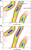
Concept of Ridge-Finding Algorithm, Related to Figure 1 (A) Ridge-finding algorithm concept including demonstrations of vision field, jump range, and directions of the current step. Contour plot of the 2D histogram generated from single-molecule interference phase values and normalized metric values. (B) Identified monotonic ridge of metric versus phase curve before phase unwrapping (red stars).
Figure S4
Figure S4
Line Profiles, Residue Plots, and Fourier Shell Correlation Resolution, Related to Figure 1 Top: four line profiles across x-y slices of microtubules shown in Figures 1D–1F. Middle: residual distances from single-molecule localizations to cylinder surface fit to four segments of the microtubule data. Bottom: Fourier shell correlation (FSC) measurement of resolution in a sub-region of ER data (right) (Figures 1B and 1C) and the combined phage data (left) (Figures 1I–1L) based on custom-written software extended to 3D from previously demonstrated Fourier ring correlation on SMSN datasets (Nieuwenhuizen et al., 2013).
Figure S5
Figure S5
Overview of an Individual Phage and Examples of Line Profiles from Figure 2, Related to Figures 1 and 2 (A) Overview of Alexa Fluor 647 labeled phages imaged by W-4PiSMSN. (B) x-z view of the entire sample showing coverslip surface and individual phages. (C–E) Cross-sections and projection of an isolated phage (arrowhead in A). (F and G) Examples of line profiles (integrated over a width of 200 nm) of the two-color image shown in Figure 2. (H) Line profile positions in Figure 2C.
Figure S6
Figure S6
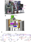
Instrument CAD Renderings and Layout of the Excitation and Diagnostic Beam, Related to Figure 1 (A and B) CAD renderings of the W-4PiSMSN instrument and the piezo-objective stack. 50/50: 50/50 beam splitter cube, PBS: polarizing beam splitter cube, Def. Mirror: deformable mirror. Please see Movie S7 for animation and more details. (C) Excitation and diagnostic beam layout. The excitation light from a polarization-maintaining single-mode fiber (solid blue line) is first collimated by an aspheric lens (f = 8 mm) and further expanded ∼6.6X to a size of ∼12 mm. This beam passes through a pair of square apertures of ∼5x5mm that cropped the center-most uniform part of the beam. An f = 500 mm lens focuses the cropped beam to the back focal plane of the top objective, uniformly illuminating an ∼18x18 μm area in the focal plane. For overview, a pair of flip mirrors route the beam through an alternative path (dashed blue line) that bypasses the apertures. The overview beam is further expanded ∼4X before being focused by the f = 500 mm lens to the back focal plane of the objective and illuminates a ∼100-μm diameter area in the focal plane. To lock the relative position of the two objectives, the laser light from a 940 nm diode laser (red solid line) is collimated by a lens to overfill the back focal plane of the bottom objective, which focuses the light to a spot in the common focal plane. This focus is imaged by the top objective producing a collimated beam propagating in the opposite direction of the excitation light. The f = 500 mm lens focuses the beam through a biplane geometry to a camera.
Figure S7
Figure S7
Molecular Density of the Cilia Membrane Protein GPCR Smoothened, Related to Figure 6 (A) Overview of a cilium, color-coded by molecular density. Density was calculated by counting the number of localizations surrounding each localization within a 100-nm radius. (B–E) Zoomed and rotated views show increased molecular density at the base of the cilium (B), at positions with potential budding vesicles (C), and in bands along the length of the cilium (D and E) which suggest potential functional arrangements of SMO.

References

    1. Aquino D., Schönle A., Geisler C., Middendorff C.V., Wurm C.A., Okamura Y., Lang T., Hell S.W., Egner A. Two-color nanoscopy of three-dimensional volumes by 4Pi detection of stochastically switched fluorophores. Nat. Methods. 2011;8:353–359. - PubMed
    1. Betzig E., Patterson G.H., Sougrat R., Lindwasser O.W., Olenych S., Bonifacino J.S., Davidson M.W., Lippincott-Schwartz J., Hess H.F. Imaging intracellular fluorescent proteins at nanometer resolution. Science. 2006;313:1642–1645. - PubMed
    1. Bewersdorf J., Schmidt R., Hell S.W. Comparison of I5M and 4Pi-microscopy. J. Microsc. 2006;222:105–117. - PubMed
    1. Briggs J.A.G. Structural biology in situ--the potential of subtomogram averaging. Curr. Opin. Struct. Biol. 2013;23:261–267. - PubMed
    1. Broeken J., Johnson H., Lidke D.S., Liu S., Nieuwenhuizen R.P.J., Stallinga S., Lidke K.A., Rieger B. Resolution improvement by 3D particle averaging in localization microscopy. Methods Appl. Fluoresc. 2015;3:014003. - PMC - PubMed

Publication types

MeSH terms