

Perception of Perspective Angles
- PMID: 27433312
- PMCID: PMC4934606
- DOI: 10.1177/2041669515593022
Perception of Perspective Angles
Abstract
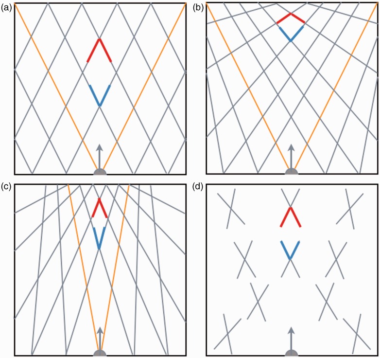
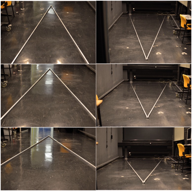
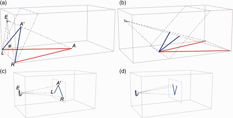
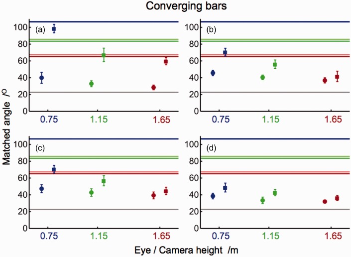
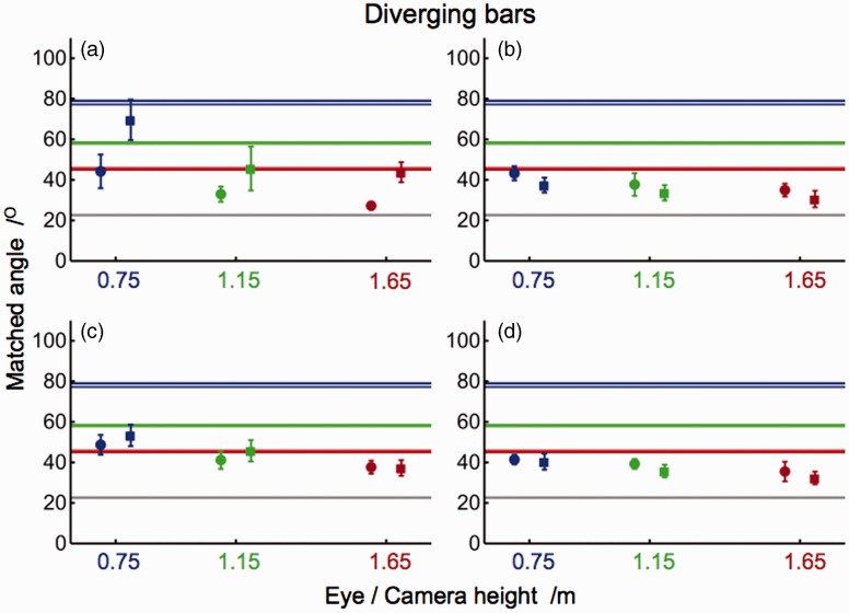
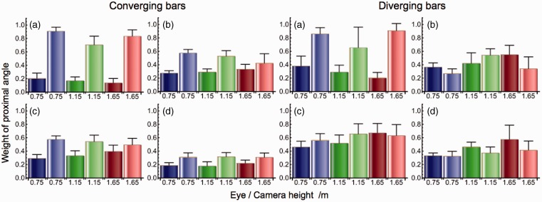
We perceive perspective angles, that is, angles that have an orientation in depth, differently from what they are in physical space. Extreme examples are angles between rails of a railway line or between lane dividers of a long and straight road. In this study, subjects judged perspective angles between bars lying on the floor of the laboratory. Perspective angles were also estimated from pictures taken from the same point of view. Converging and diverging angles were judged to test three models of visual space. Four subjects evaluated the perspective angles by matching them to nonperspective angles, that is, angles between the legs of a compass oriented in the frontal plane. All subjects judged both converging and diverging angles larger than the physical angle and smaller than the angles in the proximal stimuli. A model of shallow visual space describes the results. According to the model, lines parallel to visual lines, vanishing at infinity in physical space, converge to visual lines in visual space. The perceived shape of perspective angles is incompatible with the perceived length and width of the bars. The results have significance for models of visual perception and practical implications for driving and flying in poor visibility conditions.
Keywords: models; perspective angles; visual space.
Figures
Similar articles
-
Geometric Constraints of Visual Space.Iperception. 2021 Nov 29;12(6):20416695211055212. doi: 10.1177/20416695211055212. eCollection 2021 Nov. Iperception. 2021. PMID: 34888027 Free PMC article.
-
Perspective Space as a Model for Distance and Size Perception.Iperception. 2017 Nov 29;8(6):2041669517735541. doi: 10.1177/2041669517735541. eCollection 2017 Nov-Dec. Iperception. 2017. PMID: 29225765 Free PMC article.
-
The extent of visual space inferred from perspective angles.Iperception. 2015 Jan 6;6(1):5-14. doi: 10.1068/i0673. eCollection 2015. Iperception. 2015. PMID: 26034567 Free PMC article.
-
Foreshortening produces errors in the perception of angles pictured as on the ground.Atten Percept Psychophys. 2016 Jan;78(1):309-16. doi: 10.3758/s13414-015-1012-4. Atten Percept Psychophys. 2016. PMID: 26537919
-
Differentiating between Affine and Perspective-Based Models for the Geometry of Visual Space Based on Judgments of the Interior Angles of Squares.Vision (Basel). 2018 Jun 2;2(2):22. doi: 10.3390/vision2020022. Vision (Basel). 2018. PMID: 31735886 Free PMC article.
Cited by
-
Geometric Constraints of Visual Space.Iperception. 2021 Nov 29;12(6):20416695211055212. doi: 10.1177/20416695211055212. eCollection 2021 Nov. Iperception. 2021. PMID: 34888027 Free PMC article.
-
Equidistant Intervals in Perspective Photographs and Paintings.Iperception. 2016 Aug 17;7(4):2041669516662666. doi: 10.1177/2041669516662666. eCollection 2016 Jul-Aug. Iperception. 2016. PMID: 27698983 Free PMC article.
-
Multiple Photographs of a Perspective Scene Reveal the Principles of Picture Perception.Vision (Basel). 2018 Jun 26;2(3):26. doi: 10.3390/vision2030026. Vision (Basel). 2018. PMID: 31735889 Free PMC article.
-
Perspective Space as a Model for Distance and Size Perception.Iperception. 2017 Nov 29;8(6):2041669517735541. doi: 10.1177/2041669517735541. eCollection 2017 Nov-Dec. Iperception. 2017. PMID: 29225765 Free PMC article.
-
The Perspective Structure of Visual Space.Iperception. 2015 Oct 30;6(5):2041669515613672. doi: 10.1177/2041669515613672. eCollection 2015 Oct. Iperception. 2015. PMID: 27648222 Free PMC article.
References
-
- Blake A., Bülthoff H. H., Sheinberg D. (1993) Shape from texture: Ideal observers and human psychophysics. Vision Research 33: 1723–1737. - PubMed
-
- Blank A. A. (1953) The Luneburg theory of binocular visual space. Journal of the Optical Society of America 43: 717–727. - PubMed
-
- Blank A. A. (1961) Curvature of binocular visual space. An experiment. Journal of the Optical Society of America 51: 335–339.
-
- Braunstein M. L., Payne J. W. (1969) Perspective and form ratio as determinants of relative slant judgments. Journal of Experimental Psychology 81: 584–590.
-
- Burton H. E. (1945) The optics of Euclid. Journal of the Optical Society of America 35: 357–372.
LinkOut - more resources
Full Text Sources
Other Literature Sources
