. 2016 Jul 26;113(30):E4294-303.
doi: 10.1073/pnas.1600677113. Epub 2016 Jul 19.

Cell division plane orientation based on tensile stress in Arabidopsis thaliana

Affiliations

Cell division plane orientation based on tensile stress in Arabidopsis thaliana

Marion Louveaux et al. Proc Natl Acad Sci U S A. .

Abstract

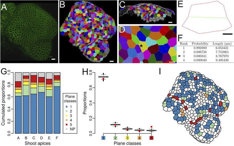
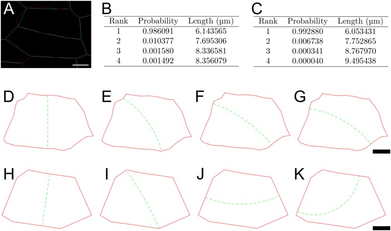
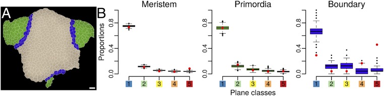
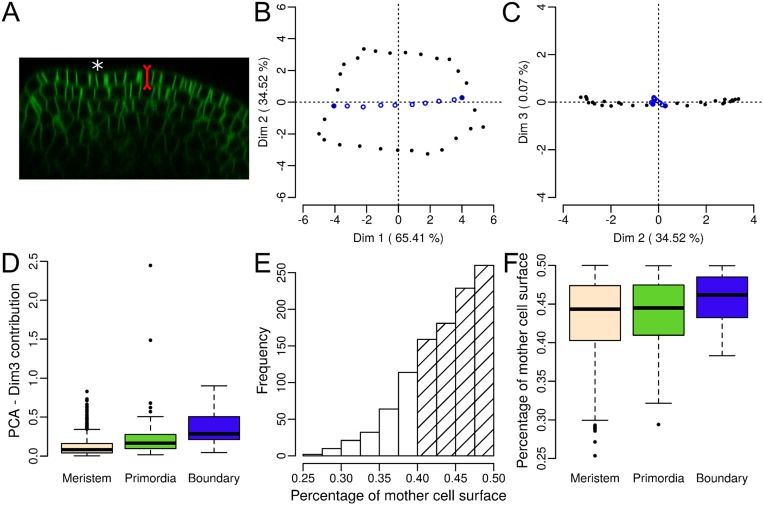
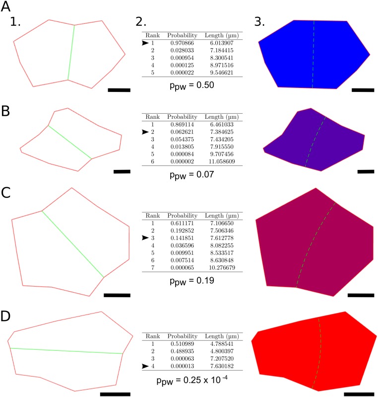
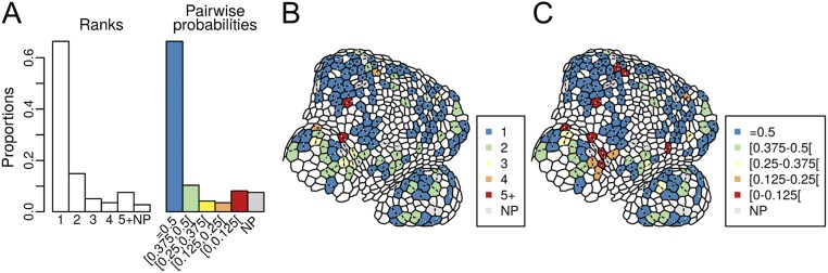
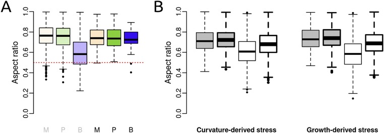
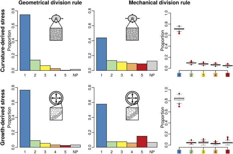
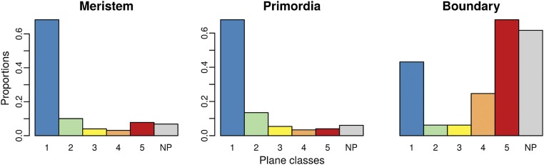
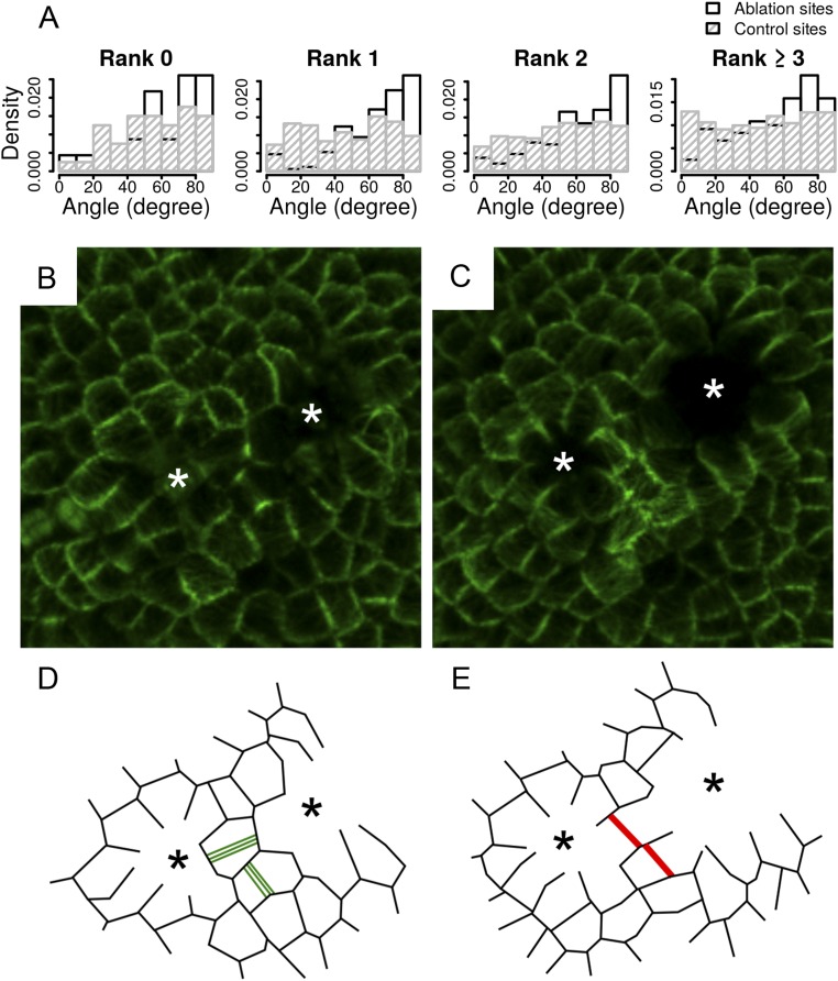
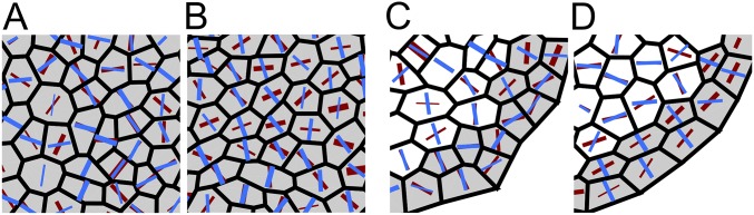
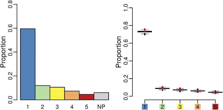
Cell geometry has long been proposed to play a key role in the orientation of symmetric cell division planes. In particular, the recently proposed Besson-Dumais rule generalizes Errera's rule and predicts that cells divide along one of the local minima of plane area. However, this rule has been tested only on tissues with rather local spherical shape and homogeneous growth. Here, we tested the application of the Besson-Dumais rule to the divisions occurring in the Arabidopsis shoot apex, which contains domains with anisotropic curvature and differential growth. We found that the Besson-Dumais rule works well in the central part of the apex, but fails to account for cell division planes in the saddle-shaped boundary region. Because curvature anisotropy and differential growth prescribe directional tensile stress in that region, we tested the putative contribution of anisotropic stress fields to cell division plane orientation at the shoot apex. To do so, we compared two division rules: geometrical (new plane along the shortest path) and mechanical (new plane along maximal tension). The mechanical division rule reproduced the enrichment of long planes observed in the boundary region. Experimental perturbation of mechanical stress pattern further supported a contribution of anisotropic tensile stress in division plane orientation. Importantly, simulations of tissues growing in an isotropic stress field, and dividing along maximal tension, provided division plane distributions comparable to those obtained with the geometrical rule. We thus propose that division plane orientation by tensile stress offers a general rule for symmetric cell division in plants.

Keywords: Arabidopsis; cell division plane; mechanical forces; meristem; vertex model.


Conflict of interest statement

The authors declare no conflict of interest.

Figures

Fig. 1.
Fig. 1.
Division planes at the shoot apex of Arabidopsis thaliana. (A) Confocal image of a LTi6B-GFP (WS-4) dissected shoot apex. (Scale bar, 10 μm.) (B) Cellular segmentation of the shoot apex shown in A with MorphoGraphX. Cells sharing the same color are daughters from a division that occurred during the last 12 h. (Scale bar, 10 μm.) (C) Segmentation is performed on the surface of the shoot apex. (Scale bar, 10 μm.) (D) Close-up of B on a young boundary region. The black asterisk points at a mother cell (i.e., two fused daughter cells), which is analyzed with Besson–Dumais script in E and F. (Scale bar, 5 μm.) (E) Flattened mother cell resulting from the 2D projection of vertices with a principal components analysis (PCA) (Fig. S2 B and C). Only the main vertices (i.e., at the junction between three cells) are kept as input for Besson–Dumais script. The new plane is colored in green. (Scale bar, 2 μm.) (F) First four planes predicted by the Besson–Dumais script for cell E. Arrowhead: The observed plane in cell E corresponds to the predicted plane of rank 3. The associated pairwise probability ppw is equal to 3.4×10⁴ and thus this cell belongs to the fifth plane class. (G) Proportion of the different plane classes in six shoot apices (total numbers of symmetrically dividing cells in the shoot apices A, B, C, D, E, and F are, respectively, 44, 71, 150, 218, 164, and 182). Class 1 corresponds to the choice of the shortest plane and class 5 corresponds to the choice of one of the longest planes. NP corresponds to an absence of match between theoretical predictions of the Besson–Dumais script and observations. (H) Comparison of observed plane proportions within the different classes (red circles) with fluctuation range obtained by bootstrap among theoretical predictions given by the Besson–Dumais script (boxplots). Planes that did not match any prediction (NP class) were excluded from this analysis. Total number of symmetrically dividing cells matching predictions on the six shoot apices (A, B, C, D, E, and F): 772. (I) Map of the shoot apex shown in A and segmented in B displaying plane classes for the divisions that occurred in the 12 h following this snapshot.
Fig. S1.
Fig. S1.
Impact of cell contour simplification on the Besson–Dumais predictions. (A) Cell contours after cellularization of the segmented mesh with a minimal cell wall length of either 1 μm, i.e., close to the real cell contour (red), or 3 μm, i.e., simplified cell contour (blue). See Materials and Methods for details. (B) Predictions of Besson–Dumais script for the four first planes of the realistic cell contour. (C) Predictions of Besson–Dumais script for the four first planes of the simplified cell contour. (D–G) Four first planes of the realistic cell contour. (H–K) Four first planes of the simplified cell contour. (Scale bars: 2 μm.)
Fig. 2.
Fig. 2.
A domain-based comparison between observations at the shoot apex and predictions of the Besson–Dumais rule. (A) Example of expert manual definition of the boundary domain (blue), the meristem domain (beige), and the primordia domains (green) on a shoot apex. (B) Comparison of observed plane proportions (red circles) with fluctuation range obtained by bootstrap among the theoretical predictions given by the Besson–Dumais script (boxplots), displayed in function of regions. Planes that were not predicted by the Besson–Dumais script (NP planes) were excluded from this analysis. Total numbers of symmetrically dividing cells in the meristem, primordium, and boundary regions, for which the observed plane was predicted by the Besson–Dumais script, are, respectively, 616, 133, and 23.
Fig. S2.
Fig. S2.
Besson–Dumais script can be applied on the surface of the shoot apex of A. thaliana. (A) Orthogonal view of a LTi6B-GFP (WS4) dissected shoot apex. The epidermis has an almost constant thickness and divisions are anticlinal to the surface. White asterisk: crease of a forming boundary. (B and C) Example of individual factor maps obtained by computing a PCA on the vertices of a divided cell for the dimensions 1 and 2 (B), and 2 and 3 (C). Vertices of the new cell wall are colored in blue. The cell is the same as in Fig. 1D (black asterisk). Dimensions 1 and 2 of the PCA are kept as input for computing the predictions of the Besson–Dumais rule (Fig. 1E). (D) Contribution of third dimension to total variability in percent (proxy of projection error) in the different regions of the shoot apex (only for symmetrically dividing cells, see E and F). (E) Distribution of the (smallest daughter cell/mother cell) surface ratios. n = 829 cell divisions. Hatched bars mark cells that divided almost symmetrically (81%). (F) Distribution of the (smallest daughter cell/mother cell) surface ratio in the different regions of the shoot apex. n = 856 cell divisions in the meristem region, 179 cell divisions in primordia, and 37 cell divisions in boundaries.
Fig. S3.
Fig. S3.
Examples of predictions given by the Besson–Dumais script. (A–D) Different cell shapes observed at the shoot apex, theoretical predictions of the Besson–Dumais script, and their choice of plane. (A–D, 1) Flattened divided cells obtained by keeping the first dimensions of a PCA computed on the 3D coordinates of the cells’ vertices. Only the main vertices, i.e., three-way junctions, are kept. Observed division planes are displayed in green. Division occurred within the last 12 h. (A–D, 2) The Besson–Dumais script computes all theoretical possible planes, displays their probability to be chosen P and their length, and provides a match between chosen plane (indicated by the arrowhead) and predictions. ppw is the pairwise probability associated with the chosen plane, defined as the ratio of Pobs, probability to observe the chosen plane, over the sum of Pobs and P1, probability to observe the shortest plane. (A–D, 3) Graphical output given by the Besson–Dumais script. Cells are colored according to the rank of the theoretical plane matching the chosen division plane. Blue, shortest plane; purple, second shortest plane; magenta, third shortest plane; and red, fourth shortest plane. Green dashed line indicates the position of the shortest theoretical plane. (Scale bars: 2 μm.)
Fig. S4.
Fig. S4.
Comparison between ranks and classes of pairwise probabilities (i.e., plane classes). (A) Proportions of plane ranks and classes of pairwise probabilities. (B and C) Representative map of plane choices in function of ranks (B) or pairwise probabilities (C).
Fig. S5.
Fig. S5.
Cell aspect ratios in real and simulated apices. (A) Observed aspect ratio of nondividing cells (gray M, P, B) and symmetrically dividing cells (black M, P, B) in the different regions of the shoot apex. M, meristem; P, primordia; B, boundary. Numbers of cells from left (nondividing meristem cells) to right (dividing boundary cells) are, respectively, 6,510, 1,695, 996, 654, 142, and 33. (B) Aspect ratio of cells in simulated tissues, when mechanical stress is derived from curvature or growth. Cells divided according to either the geometrical or the mechanical division rule (respectively gray or white boxplots). The mechanical stress field is either anisotropic or isotropic (respectively thin or thick lines). Numbers of cells from left (anisotropic curvature-derived stress field and geometrical division rule) to right (isotropic growth-derived stress field and mechanical division rule) are, respectively, 4,002, 4,000, 4,003, 4,003, 1,135, 1,329, 1,284, and 1,377.
Fig. 3.
Fig. 3.
Comparison of two division rules in a simulated boundary region. Shown are plane class proportions in the different simulated growing tissues, submitted either to curvature-derived or to growth-derived mechanical stress and following a geometrical or a mechanical division rule. For the simulations with the mechanical division rule, a bootstrap among theoretical predictions given by the Besson–Dumais script was done to compare observed plane proportions in simulated tissues (red circles) with fluctuations range (boxplots).
Fig. S6.
Fig. S6.
Proportions of plane classes in each region of the shoot apex. Numbers of symmetrically dividing cells in the meristem, primordia, and boundary regions are, respectively, 654, 142, and 33.
Fig. 4.
Fig. 4.
Effects of mechanical perturbation on division plane orientation. (A) Angle α between the principal stress axis (simulated tissues) or the new cell wall (real tissues) and radius of the ablation. α is measured in each cell adjacent to the ablation site and on cells adjacent to these cells. (B) Angle α before and after ablation on simulated tissues. Close-up on a simulated tissue shows the direction of the maximal tension (black bars) within the cells neighboring an ablation site. Cells are colored according to the value of angle α, from blue (0°) to red (90°). (C) Confocal image of LTi6B-GFP (WS-4) dissected shoot apex 30 min after pulsed UV laser ablation. White arrowhead points at ablation site. White asterisk: same cell as in E. (D and E) New cell walls formed within 48 h (red lines) on (D) control and (E) ablated LTi6B-GFP (WS-4) dissected shoot apex. White arrowhead points at ablation site. Yellow arrowheads: boundary region. White asterisk: same cell as in C. (F) Distribution of the angle α in adjacent dividing cells of 36 ablated meristems. Control: 92 cells from three meristems are taken as “ablation site” and α is computed in the adjacent dividing cells (see Fig. S7 for a detailed analysis of the distribution of angle α in function of the location of ablation site on the meristem).
Fig. S7.
Fig. S7.
Cell division after ablation. (A) Distribution of the angle between the new cell wall and radius of the ablation in function of the localization of the ablation or control site on the meristem. Ranks are defined as concentric adjacent cell circles surrounding the center of the meristem. New cell divisions are always more circumferential after an ablation than in the controls. (B–E) Impact of a double ablation on division. (B and C) Confocal images of a clv3-2 GFP-MBD shoot apical meristem (B) 15 min after ablation and (C) 24 h after ablation. White asterisks point at the ablation sites. (D and E) Schematic drawings of B and C. Green lines represent the PPBs. Red lines represent the new cell walls. Black asterisks point at ablation sites. After ablation, one of the cells divided orthogonally to the preexisting PPB.
Fig. S8.
Fig. S8.
Cell divisions in flattened boundaries. (A) Setup used to flatten apices and 3D reconstruction of a flattened naked meristem. (B and C) Examples of flat boundaries in meristems expressing the p35S::GFP-MBD construct, revealing the microtubule network. Red asterisks mark the growing organs. Note the presence of aligned cortical microtubules in the boundary domain, matching the orientation of phragmoplast (B) and PPB (C). New cell divisions are marked with dotted red lines. All divisions in these boundaries follow maximal tensile stress direction, whereas many do not follow the shortest path. (C, Lower) The close-ups are extracted from the green boxes in C, Upper.
Fig. S9.
Fig. S9.
Cell divisions in inflorescence stems from NPA-grown in vitro plants. (A) Predicted tensile stress pattern in a pressurized cylinder: Circumferential tensile stress is two times higher than axial tensile stress. (B) Naked stem after NPA treatment as viewed from the side, before and 5 d after oryzalin treatment, revealing the fast growth rate of the apical part of the stem. (C) Side view of an inflorescence stem. (D) Close-up from C. New cell divisions are marked with a red dotted line. (E) Cell division in a stem expressing the p35S::GFP-MBD construct: A PPB is marked with two red arrows and follows the circumferential, maximal, tensile stress direction.
Fig. S10.
Fig. S10.
Mechanical stress and cell geometry in simulated tissues. (A–D) Stress and shape anisotropy in different simulated tissues, submitted to (A and B) curvature-derived or (C and D) growth-derived, (A and C) isotropic or (B and D) anisotropic mechanical stress. Red bars are oriented in the direction of maximal stress and their widths are proportional to the stress anisotropy. Blue bars are oriented in the direction of the short axis and their widths are proportional to the shape anisotropy. The anisotropy of a tensor is computed as the difference between its eigenvalues λ1 and λ2 normalized by (λ12+λ22).
Fig. 5.
Fig. 5.
Plane class proportions and bootstrap on simulated tissues growing in an isotropic stress field and following the mechanical division rule. Plane class proportions (barplot) and bootstrap among theoretical predictions given by the Besson–Dumais script were done to compare observed plane proportions in simulated tissues (red circles) with fluctuation range (boxplots).
Fig. 6.
Fig. 6.
Tensile stress prescribes cell division plane orientation in symmetrically dividing cells. (Upper) When growth is locally homogeneous and shape locally spherical, the tensile stress pattern in cell walls can be derived from cell geometry only, assuming that plant cells behave like pressure vessels. In that case, maximal tension will be circumferential in elongated, cylindrical cells, leading to transverse division plane orientation, as in Errera’s rule. (Lower) When growth becomes heterogeneous and/or tissue shape is anisotropic, tensile stress in cell walls may be biased by tissue stress. For instance, in the meristem boundary, tissue curvature and differential growth prescribe highly anisotropic tensile stresses and cells divide along the axis of the boundary, relatively independent of cell shape.

Comment in

  • doi: 10.1073/pnas.1609309113

References

    1. Sahlin P, Jönsson H. A modeling study on how cell division affects properties of epithelial tissues under isotropic growth. PLoS One. 2010;5(7):e11750. - PMC - PubMed
    1. Hofmeister W. Zusatze und berichtigungen zu den 1851 veröffentlichen untersuchungen der entwicklung höherer kryptogamen. Jahrbucher fur Wissenschaft und Botanik. 1863;3:259–293. German.
    1. Sachs J. Uber die Anordnung der Zellen in jungsten Pflanzentheilen. Arbeiten des Botanisches Institut Wurzburg. 1878;2:46–104. German.
    1. Errera L. Über Zellformen und Seifenblasen. Botanisches Centralblatt. 1888;34:395–398. German.
    1. Besson S, Dumais J. Stochasticity in the symmetric division of plant cells: When the exceptions are the rule. Front Plant Sci. 2014;5:538. - PMC - PubMed

Publication types

LinkOut - more resources