. 2016 Jul 20;11(7):e0159526.
doi: 10.1371/journal.pone.0159526. eCollection 2016.

Diffusive Silicon Nanopore Membranes for Hemodialysis Applications

Affiliations

Diffusive Silicon Nanopore Membranes for Hemodialysis Applications

Steven Kim et al. PLoS One. .

Abstract

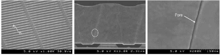
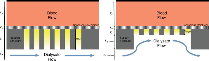
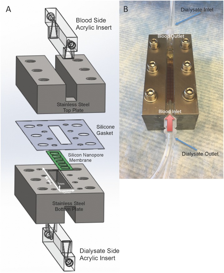
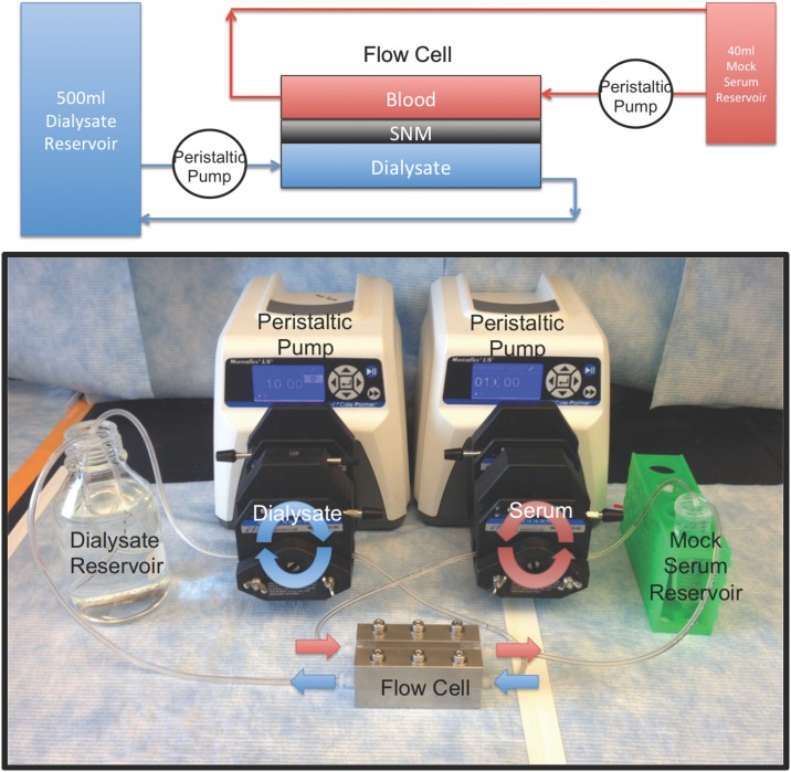
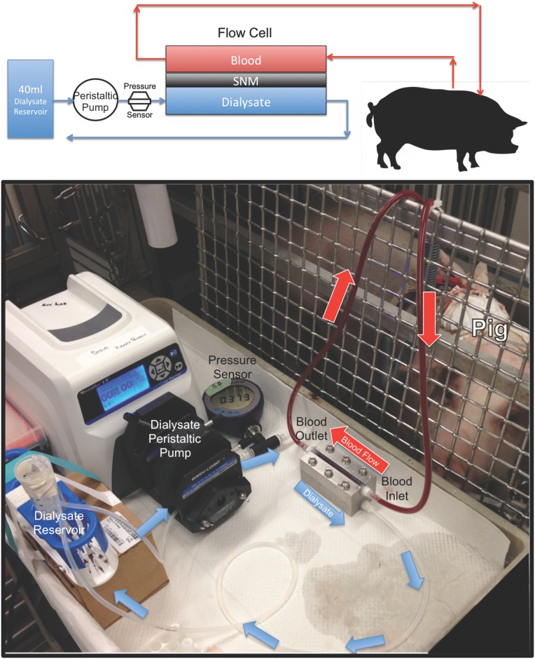
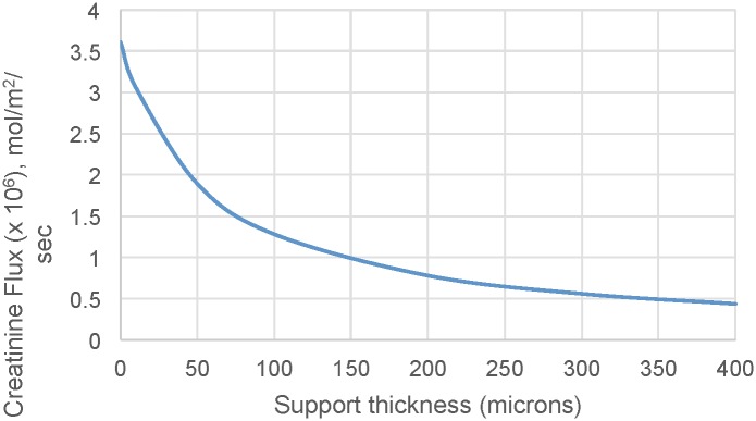
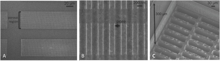
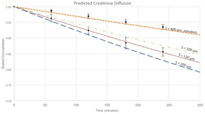
Hemodialysis using hollow-fiber membranes provides life-sustaining treatment for nearly 2 million patients worldwide with end stage renal disease (ESRD). However, patients on hemodialysis have worse long-term outcomes compared to kidney transplant or other chronic illnesses. Additionally, the underlying membrane technology of polymer hollow-fiber membranes has not fundamentally changed in over four decades. Therefore, we have proposed a fundamentally different approach using microelectromechanical systems (MEMS) fabrication techniques to create thin-flat sheets of silicon-based membranes for implantable or portable hemodialysis applications. The silicon nanopore membranes (SNM) have biomimetic slit-pore geometry and uniform pores size distribution that allow for exceptional permeability and selectivity. A quantitative diffusion model identified structural limits to diffusive solute transport and motivated a new microfabrication technique to create SNM with enhanced diffusive transport. We performed in vitro testing and extracorporeal testing in pigs on prototype membranes with an effective surface area of 2.52 cm2 and 2.02 cm2, respectively. The diffusive clearance was a two-fold improvement in with the new microfabrication technique and was consistent with our mathematical model. These results establish the feasibility of using SNM for hemodialysis applications with additional scale-up.


Conflict of interest statement

Competing Interests: The authors have the following interests. Shuvo Roy and William Fissell have ownership in Silicon Kidney, a start-up company that will advance the commercialization of silicon membrane technology. This ownership might possibly result in potential financial benefit. Charles Blaha and Nathan Wright were also employed by Silicon Kidney, LLC. Benjamin Chui is affiliated with Ben Chui Consulting and Ken Goldman with H-Cubed. Patent to declare: “Low Resistance Microfabricated Filter” and the publication number is US2015/0090661. There are no products in development or marketed products to declare. This does not alter the authors’ adherence to all the PLOS ONE policies on sharing data and materials, as detailed online in the guide for authors.

Figures

Fig 1
Fig 1. SEM Images of Standard Silicon Nanopore Membranes for hemofiltration.
(Left) Top view showing the uniform array of slit pores. (Center) Cross-section image showing the non-tortuous path of the pore. (Right) A close up image of the slit pore showing the smooth surface characteristics. Reprinted from W. H Fissell et al. / Journal of Membrane Science under a CC BY license, with permission from Elsevier, original copyright 2009.
Fig 2
Fig 2. Support Structure Reduction.
(Left) Schematic of the standard-SNM with a 400 μm thick support structure that results in a longer diffusion path and decreased diffusive transport. The mass transfer coefficients for blood (kb), membrane (km), support structure (ks) and dialysate (kd) are shown in the figure. (Right) Depicts the diffusive-SNM with a reduced support structure (100 μm) resulting in improved diffusive clearance due to the decreased resistance from the support structure. The mass transfer coefficients for kd is rework to take into account the cavity (kd, cavity) and the channel (kd, channel).
Fig 3
Fig 3. The step-wise process for the fabrication of diffusive-SNM.
Using photolithography and a new two-step DRIE process that allows for reduction in the underlying support structure of the membranes. The process steps A through L are described in detail within the membrane fabrication section.
Fig 4
Fig 4. Single channel dialysate flow cell.
Fig (A) shows construction of the flow cell. An acrylic insert is placed into a stainless steel plate to form the flow channels. A silicone gasket is used to form a watertight seal around the SNM. The SNM is mounted onto the bottom stainless steel plate and the dialysate side acrylic insert forms the bottom channel. The white arrows indicate the flow path dimension of 80 x 10 x 1 mm (length x width x height). The photo (B) shows the fully constructed flow cell with the blood inlet and outlet labeled on the top plate. The red arrow shows the direction of blood flow. The dialysate flows in a counter-current fashion and the blue arrow labels the dialysate inlet and outlet.
Fig 5
Fig 5. In vitro diffusion study.
The top panel is a schematic of the in vitro diffusion study. Mock serum (40 ml) was pumped via a peristaltic pump over the topside of the SNM within the flow cell. The dialysate (500 ml) flows in a countercurrent direction via another peristaltic pump over the backside of the SNM. The bottom panel is a photograph of the diffusion study with the red arrows showing the direction of flow of the mock serum and the blue arrows showing the direction of flow of the dialysate.
Fig 6
Fig 6. Extracorporeal diffusion study.
The top panel is a figure of the extracorporeal experiment for diffusion experiments. Blood from the pig is circulated via the arterial-venous pressure differential over the top of the SNM. The dialysate flowed in a counter-current direction via a peristaltic pump over the backside of the SNM. A pressure sensor was used to measure the pressure on the dialysate side. The bottom panel shows a photograph of the extracorporeal experiment. Blood tubing was attached to the arterial catheter of the pig and blood flowed via the arterial-venous pressure differential through the flow cell. The blood was returned back to the pig via blood tubing attached to the venous catheter. The red arrows indicate the direction of blood flow. Dialysate flowed in a counter-current direction via a peristaltic pump. The blue arrows indicate the direction of dialysate flow. A pressure sensor measures the pressure on the dialysate side.
Fig 7
Fig 7. The impact of support structure thickness on creatinine flux.
The graph shows the predicted change in creatinine flux across the SNM with varying support structure thicknesses.
Fig 8
Fig 8. CFD Analysis of Dialysate Flow.
The streamlines show the fluid velocity as it passes under the 300 μm reduced support structure of the SNM. The channel height is set to 1 mm. The various flow rates demonstrate that the flow is quickly fully developed within the cavity, except at higher flow rates (100 ml/min) when stagnant regions form under the upstream 1/3 of the backside cavity.
Fig 9
Fig 9. Photographs of diffusive-SNM.
(A) Shows the blood-contacting surface (front side) of the SNM. The total dimensions of the SNM are 65 x 10 mm. The functioning membrane portions with pores are the 3 mm x 3 mm squares arranged within the chip. The effective membrane surface area is 2.52 cm2. The remaining regions are solid silicon support. (B) The dialysate-contacting surface (backside) of the SNM. (C) Close-up of the 3 mm x 3 mm backside and the recessed cavity formed by the new two-step DRIE process.
Fig 10
Fig 10. Scanning electron microscopy.
(A) Depicts the porous region within a 3 mm x 3 mm portion of the SNM. Each 3 mm x 3 mm has a total of 370 porous regions that are composed of slit-pores. (B) Depicts a pore (black arrow) within a porous region. Each porous region contains ~11,000 pores. The total number of pores on an SNM is 1.14 x 10⁸. (C) Depicts the backside of the SNM and demonstrates the 300 μm reduced support structure after the two-step DRIE process.
Fig 11
Fig 11. Creatinine Transport Model of SNM.
The graph shows the scaled concentration decrease over time for creatinine via diffusion only. The colored lines represent the predicted concentration over time at various support structure heights (400, 200, 150 and 100 μm) based on the mathematical model for diffusive-SNM and standard-SNM. The black circles represent experimental data obtained in vitro for standard-SNM design with 400 μm support structure. The black diamonds represent experimental data obtained in vitro for the diffusive-SNM design with support structures between 100–150 μm.

References

    1. United States Renal Data System. 2015 USRDS annual data report: Epidemiology of kidney disease in the United States. In: National Institutes of Health, National Institute of Diabetes and Digestive and Kidney Diseases, editor. Bethesda, MD: National Institutes of Health, National Institute of Diabetes and Digestive and Kidney Diseases; 2015.
    1. Finkelstein FO, Schiller B, Daoui R, Gehr TW, Kraus MA, Lea J, et al. At-home short daily hemodialysis improves the long-term health-related quality of life. Kidney Int. 2012;82: 561–569. 10.1038/ki.2012.168 - DOI - PubMed
    1. Kimmel PL, Peterson RA, Weihs KL, Simmens SJ, Alleyne S, Cruz I, et al. Multiple measurements of depression predict mortality in a longitudinal study of chronic hemodialysis outpatients. Kidney Int. 2000;57: 2093–2098. - PubMed
    1. US Department of Health and Human Services. OPTN: Data Organ Procurement and Transplantation Network. 2013.
    1. Saran R, Bragg-Gresham JL, Levin NW, Twardowski ZJ, Wizemann V, Saito A, et al. Longer treatment time and slower ultrafiltration in hemodialysis: associations with reduced mortality in the DOPPS. Kidney Int. 2006;69: 1222–1228. - PubMed