. 2016 Jul;13(120):20160408.
doi: 10.1098/rsif.2016.0408.

Elastic membranes in confinement

Affiliations

Elastic membranes in confinement

J B Bostwick et al. J R Soc Interface. 2016 Jul.

Abstract

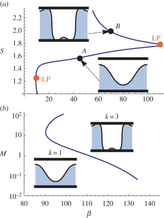
An elastic membrane stretched between two walls takes a shape defined by its length and the volume of fluid it encloses. Many biological structures, such as cells, mitochondria and coiled DNA, have fine internal structure in which a membrane (or elastic member) is geometrically 'confined' by another object. Here, the two-dimensional shape of an elastic membrane in a 'confining' box is studied by introducing a repulsive confinement pressure that prevents the membrane from intersecting the wall. The stage is set by contrasting confined and unconfined solutions. Continuation methods are then used to compute response diagrams, from which we identify the particular membrane mechanics that generate mitochondria-like shapes. Large confinement pressures yield complex response diagrams with secondary bifurcations and multiple turning points where modal identities may change. Regions in parameter space where such behaviour occurs are then mapped.

Keywords: bifurcation; biological mechanics; interfaces; membranes; mitochondrion.


Figures

Figure 1.
Figure 1.
Experimental image of a typical mitochondrion showing a large inner membrane confined by a smaller outer membrane. (Reproduced from Fawcett [1].) (Online version in colour.)
Figure 2.
Figure 2.
Definition sketch. An interface ∂D with tension β and length S, defined in Cartesian coordinates y = h(x), encloses a domain D with volume V and pressure p that is confined between two solid walls at y = ±H. (Online version in colour.)
Figure 3.
Figure 3.
Unconfined (M = 0) long-wave approximation: (a) bifurcation diagram plotting arclength S against tension β and (b) the family of solutions along the k = 1 branch. (Online version in colour.)
Figure 4.
Figure 4.
Confined (M = 0.1) long-wave approximation: (a) response diagram for the k = 1 solution in the long-wave approximation exhibits membrane stiffening upon an increase in length S compared with the unconfined (dashed) solution. (b) Membrane shapes at points A and B illustrate the effect of the confinement pressure. Here V = 0.5, M = 0.1. (Online version in colour.)
Figure 5.
Figure 5.
(a) Bifurcation diagram plotting arclength S against tension β and (b) membrane shapes with wavenumbers k = 1, 2, 5 at points A, B, C of part (a) for M = 0.1, V = 0.5. (Online version in colour.)
Figure 6.
Figure 6.
The locus of bifurcation points computed by continuation in the (a) confinement force M for V = 0.5, (b) volume V and (c) pressure p with M = 0.1. (Online version in colour.)
Figure 7.
Figure 7.
(a) Response diagram for a membrane subject to strong confinement forces M = 1 exhibits two turning (LP) points. Increasing the arclength S along the branch shows the wavenumber identity changes from k = 1 (A) to k = 3 (B) as the second fold is traversed. (b) The locus of LPs is continued in the Mβ space. Representative shapes are shown as insets. (Online version in colour.)
Figure 8.
Figure 8.
(a) Bifurcation (BP) off the k = 2 primary branch for M = 0.25 exhibits solutions that preserve wavenumber identity, but have different symmetry. (b) The locus of SBs is continued in the Mβ space. (Online version in colour.)
Figure 9.
Figure 9.
(a) Response diagram plotting pressure p against arclength S with limiting membrane shape inset and (b) parametric plot of volume V against arclength S for fixed tension β = 10 and M = 0.001. (Online version in colour.)
Figure 10.
Figure 10.
Response diagram in the long-wave limit for a membrane in the presence of hydration stresses M = 10, λ = 10−2 by plotting arclength S against tension β. The membrane shape (inset) for S = 3 penetrates the solid for this set of parameters, which is indicative of a soft potential. (Online version in colour.)
Figure 11.
Figure 11.
Membrane shapes (k = 1, 2) in the long-wave limit in the presence of hydration stresses with M = 10 for fixed arclength S = 3, as it depends upon the characteristic length λ, penetrate the solid for certain values of λ which cannot be predicted a priori. (Online version in colour.)

References

    1. Fawcett D. 1981. The cell. Philadelphia, PA: W. B. Saunders Co.
    1. Bo L, Waugh RE. 1989. Determination of bilayer membrane bending stiffness by tether formation from giant, thin-walled vesicles. Biophys. J. 55, 509–517. (10.1016/S0006-3495(89)82844-9) - DOI - PMC - PubMed
    1. Ghochani M, Nulton J, Salamon P, Frey T, Rabinovitch A, Baljon A. 2010. Tensile forces and shape entropy explain observed crista structure in mitochondria. Biophys. J. 99, 3244–3254. (10.1016/j.bpj.2010.09.038) - DOI - PMC - PubMed
    1. Vella D, Mahadevan L. 2005. The ‘Cheerios effect’. Am. J. Phys. 73, 817–825. (10.1119/1.1898523) - DOI
    1. Vella D. 2015. Floating versus sinking. Annu. Rev. Fluid Mech. 47, 115–135. (10.1146/annurev-fluid-010814-014627) - DOI

Publication types

MeSH terms

LinkOut - more resources