. 2016 Oct:104:168-81.
doi: 10.1016/j.biomaterials.2016.06.001. Epub 2016 Jun 29.

Surface delivery of tunable doses of BMP-2 from an adaptable polymeric scaffold induces volumetric bone regeneration

Affiliations

Surface delivery of tunable doses of BMP-2 from an adaptable polymeric scaffold induces volumetric bone regeneration

Michael Bouyer et al. Biomaterials. 2016 Oct.

Abstract

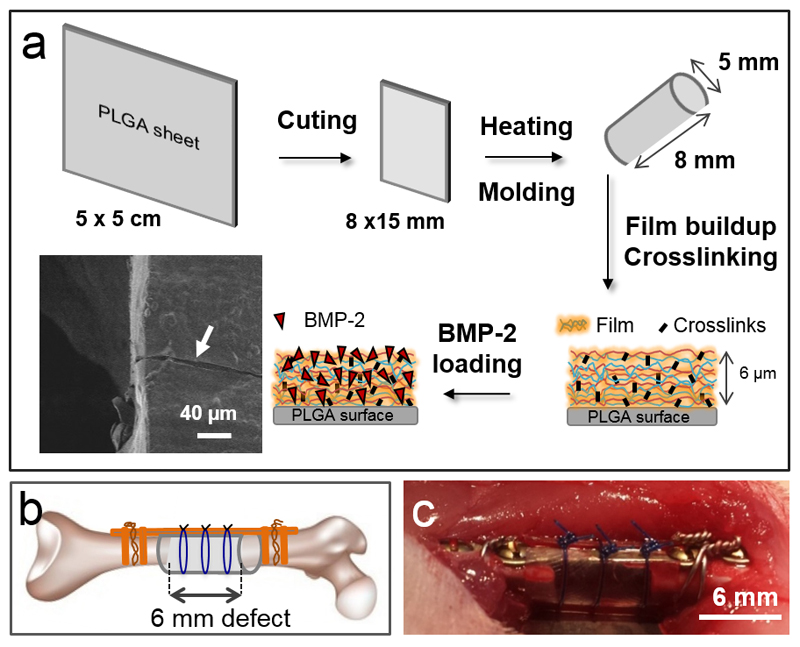
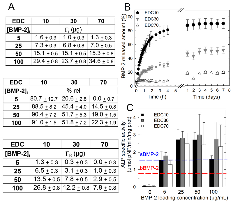
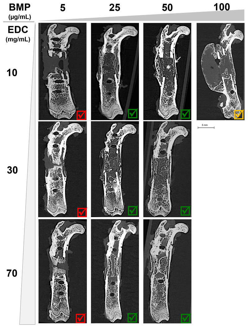
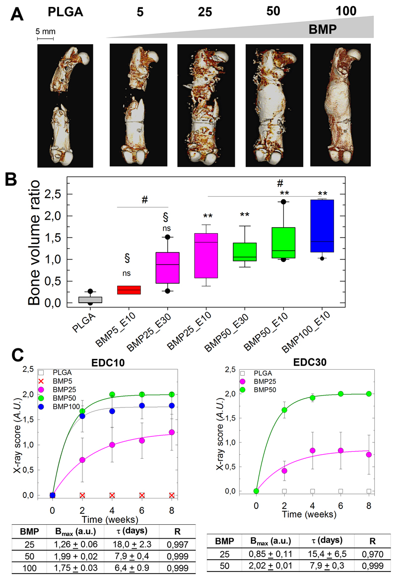
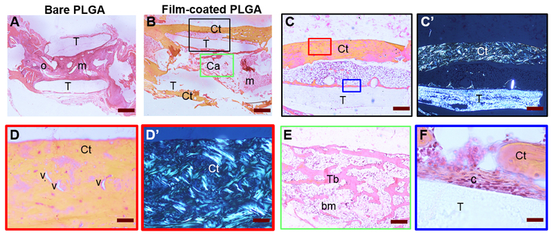
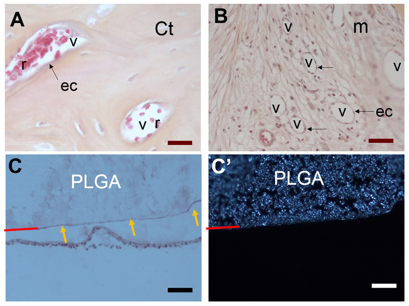
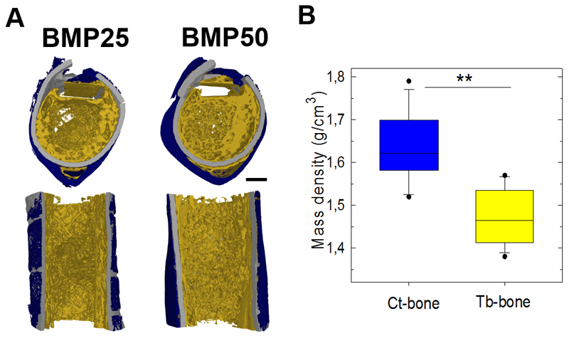
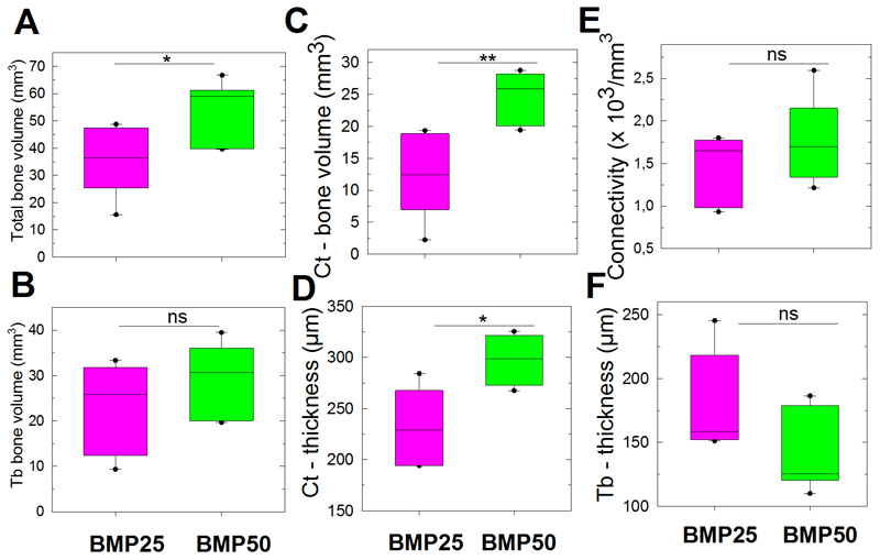
The rapid and effective bone regeneration of large non-healing defects remains challenging. Bioactive proteins, such as bone morphogenetic protein (BMP)-2, are proved their osteoinductivity, but their clinical use is currently limited to collagen as biomaterial. Being able to deliver BMP-2 from any other biomaterial would broaden its clinical use. This work presents a novel means for repairing a critical size volumetric bone femoral defect in the rat by combining a osteoinductive surface coating (2D) to a polymeric scaffold (3D hollow tube) made of commercially-available PLGA. Using a polyelectrolyte film as BMP-2 carrier, we tune the amount of BMP-2 loaded in and released from the polyelectrolyte film coating over a large extent by controlling the film crosslinking level and initial concentration of BMP-2 in solution. Using microcomputed tomography and quantitative analysis of the regenerated bone growth kinetics, we show that the amount of newly formed bone and kinetics can be modulated: an effective and fast repair was obtained in 1-2 weeks in the best conditions, including complete defect bridging, formation of vascularized and mineralized bone tissue. Histological staining and high-resolution computed tomography revealed the presence of bone regeneration inside and around the tube with spatially distinct organization for trabecular-like and cortical bones. The amount of cortical bone and its thickness increased with the BMP-2 dose. In view of the recent developments in additive manufacturing techniques, this surface-coating technology may be applied in combination with various types of polymeric or metallic scaffolds to offer new perspectives of bone regeneration in personalized medicine.

Keywords: Biomedical engineering; Bone morphogenetic proteins; Functional coatings; Orthopedic materials; Tissue engineering.


Figures

Figure 1
Figure 1. Experimental design of the in vivo experiments in rat femoral critical-size defect.
(A) Procedure for the film buildup on the PLGA membrane: the PLGA sheet is cut to the appropriate size and molded into a hollow tube. The film is built on the tube, crosslinked and post-loaded with BMP-2. The film-coated membrane can be visualized by scanning electron microscopy. Both EDC crosslinking and BMP-2 loaded amounts are adjustable parameters. A scanning electron microscopy side view of the film-coated PLGA membrane reveals the presence of the film after scratching (white arrow). (B) Scheme of the critical defect with the PLGA membrane shaped as a hollow tube and fixed with external fixators (plate and screws) and suture wires. (C) Post-operative view of the implanted PLGA tube maintained by suture wires.
Figure 2
Figure 2. In vitro evaluation of BMP-2 loading, release and bioactivity as functions of BMP-2 initial loading concentration and film crosslinking extent (EDC).
(A) BMP-2 incorporated amounts (ΓI,μg), % of BMP-2 released and released amount remaining after 7 days of in vitro release (ΓR, μg) as a function of the initial BMP-2 concentration in the loading solution and for different crosslinker concentrations (EDC10, 30 and 70). (B) BMP-2 release profiles in physiological buffer as a function of time over 8 days, depending on the film cross-linking extent. Data represent the means ± SEM of 3 experiments. (C) In vitro ALP bioactivity of BMP-2-loaded films coated on PLGA membranes. Two controls were performed: BMP-2 adsorbed onto a bare PLGA membrane (red line “bBMP-2) and BMP-2 added in the GM for cells seeded directly on bare PLGA membranes (blue line “sBMP-2). Data represent the means ± SEM of 2 experiments (3 samples per experimental condition).
Figure 3
Figure 3. CμCT images at 8 weeks obtained for increasing EDC crosslinking (EDC10, EDC30 and EDC70) and BMP-2 doses from 5 to 100 μg/mL.
Sagittal cross-sections are shown for the 10 pre-screened conditions (see Table 1). All EDC5 conditions lead to an inappropriate bone formation and are marked by a red cross. Those that lead to a satisfactory bone regeneration are marked by a green V sign. The EDC10/BMP100 condition is marked by an orange V sign as it lead to a bone shell formation if the hematoma was not punctured.
Figure 4
Figure 4. Quantitative analysis of bone regeneration by X-ray and CμCT. Quantitative analysis of bone regeneration by X-ray and CμCT.
(A) Representative 3D CμCT reconstructions taken at 8 weeks after implantation for EDC with increasing doses of BMP-2 (BMP5 to BMP100) and control PLGA (scale bars, 5 mm). (B) Box plot representation of the bone volume ratio at 8 weeks (n = 8, except for BMP5/EDC10 with n = 2) for the EDC10 and EDC30 films with increasing BMP-2 doses from BMP5 to BMP100. BMP25 groups are in pink, BMP50 in green and BMP100 in blue (for simplification of the X-axis, the EDC is abbreviated by E). All groups were compared to the PLGA group. *P < 0.05, **P < 0.01, # indicates no significant difference between pairs, § indicates significant difference (P < 0.05) compared to BMP100 group, ns indicates no significant difference compared to PLGA group (pairwise Mann-Whitney U test) (C) X-ray scores calculated from X-ray images as a function of time and corresponding exponential fits to the data (colored lines) for EDC10 (D) and EDC(30) groups. The plateau value (Bmax), characteristic time τ (days) deduced from the fits and fit quality R are given in the corresponding tables.
Figure 5
Figure 5. Histological analysis.
Representative bone tissue cross-sections of (A) control PLGA and (B) film-coated PLGA at 8 weeks post-implantation. (A) The PLGA tube (T) was found between the two femoral edges: (A) in mesenchymal tissue (m) and at the ossification point (o). In contrast (B), cortical bone (Ct) and cancellous bone (Ca) with bone marrow (bm) were found outside and inside the film-coated PLGA tube, bridging the initial defect. (C) Corresponds to a larger magnification of the black box in (B); (D) to a larger magnification of red box in (C) with visible blood vessels (v); (C’, D’) are the corresponding polarized light micrographs showing the birefringence of collagen strands. (E) Magnified view of trabecular bone, corresponding to green box in (B), in which bone marrow is present. (F) Magnified view of the tube/tissue interface in (C) with adhesive cells (c) observed on the film-coated PLGA. Scale bars are as follows: (A, B): 800 μm; (C, C’): 400 μm; (D, D’, E): 80 μm; (F): 20 μm.
Figure 6
Figure 6. Histological observations of vascularization of regenerated bone tissue and of PLGA/tissue interface.
High resolution histological observations reveals the presence of numerous vessels (v) in the regenerated bone: (A) cortical (Ct) bone and (B) mesenchymal tissue (m); The vessels (v) can clearly be identified by the presence of endothelial cells (ec, indicated by black arrows) lining along the vessel walls and by red blood cells (r) with their characteristic discoidal shape and absence of nucleus. (C,C’) Imaging of PLGA/tissue interface of the same zone with optical microscopy (C ) and polarized light (C’). Polarized light shows the birefringence of PLGA, which is due to its semi-crystalline structure. The PLGA surface is indicated by a red line. To note, the PLGA surface appears diffuse when observed by polarized microscopy (C’) whereas a thin continuous line is visible in (C, orange arrows). This continuous lines corresponds to the polyelectrolyte film coating at the PLGA surface (with a thickness of only few μm).
Figure 7
Figure 7. High-resolutiofin morphological analysis of bone regeneration using SRμCT at 8 weeks after implantation.
(A) Representative transversal and sagittal cross-sections of 3D SRμCT reconstructions of film-coated PLGA tubes at BMP-2 doses of BMP25 and BMP50 (scale bars, 1 mm). (B) Bone mass density of Ct-bone and Tb-bone as determined by SRμCT. Data are presented by boxplot for all samples pooled together, irrespective of the EDC or BMP-2 dose (n = 12). ** P < 0.01 (Wilcoxon paired test).
Figure 8
Figure 8. Bone volumes quantified using SRμCT.
Data are presented by boxplots at 8 weeks after implantation for films loaded with BMP25 or BMP50, the EDC groups being pooled together (n = 6 for each BMP concentration). (A) Total bone volume. (B) Tb-bone volume. (C) Ct bone volume and (D) Ct thickness. (E) Connectivity and (F) trabecular thickness in Tb bone. * P < 0.05, **P < 0.01; ns, not significant (Mann-Whitney U test).

References

    1. Laurencin C, Khan Y, El-Amin SF. Bone graft substitutes. Expert review of medical devices. 2006;3:49–57. - PubMed
    1. Giannoudis PV, Dinopoulos H, Tsiridis E. Bone substitutes: an update. Injury. 2005;36(Suppl 3):S20–7. - PubMed
    1. Janicki P, Schmidmaier G. What should be the characteristics of the ideal bone graft substitute? Combining scaffolds with growth factors and/or stem cells. Injury. 2011;42(Suppl 2):S77–81. - PubMed
    1. Puppi D, Chiellini F, Piras AM, Chiellini E. Polymeric materials for bone and cartilage repair. Prog Polym Sci. 2010;35:403–440.
    1. Lee K, Silva EA, Mooney DJ. Growth factor delivery-based tissue engineering: general approaches and a review of recent developments. J R Soc Interface. 2011;8:153–70. - PMC - PubMed

Publication types

MeSH terms

Substances