

Strain and rate-dependent neuronal injury in a 3D in vitro compression model of traumatic brain injury
- PMID: 27480807
- PMCID: PMC4969749
- DOI: 10.1038/srep30550
Strain and rate-dependent neuronal injury in a 3D in vitro compression model of traumatic brain injury
Abstract
In the United States over 1.7 million cases of traumatic brain injury are reported yearly, but predictive correlation of cellular injury to impact tissue strain is still lacking, particularly for neuronal injury resulting from compression. Given the prevalence of compressive deformations in most blunt head trauma, this information is critically important for the development of future mitigation and diagnosis strategies. Using a 3D in vitro neuronal compression model, we investigated the role of impact strain and strain rate on neuronal lifetime, viability, and pathomorphology. We find that strain magnitude and rate have profound, yet distinctively different effects on the injury pathology. While strain magnitude affects the time of neuronal death, strain rate influences the pathomorphology and extent of population injury. Cellular injury is not initiated through localized deformation of the cytoskeleton but rather driven by excess strain on the entire cell. Furthermore we find that, mechanoporation, one of the key pathological trigger mechanisms in stretch and shear neuronal injuries, was not observed under compression.
Figures
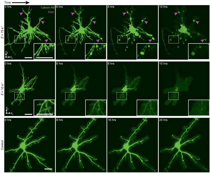
 (top) and
  (middle), and a no-impact control. Arrows (magenta) indicate locations of bleb formation. Scale bars, 20 µm.
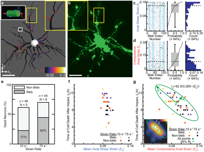
 (bottom). Scale bar, 20 µm. (c) (left) Axial shear strain Es at each bleb location for eight neurons at
  . Alternate shading (light blue) pattern denotes data points for each cell at
  . (center) Corresponding cumulative probability distribution function with box and whisker plot. Probability of finding a bleb given a certain value of Es is multiplied by 64% (the percentage of bleb formation at
  ). (right) Corresponding histogram normalized by total count. (d) The same computation in (c) for the compressive axial strain Ec. (e) Stacked bar plots of the percentage of neuron death for
  (n = 46, N = 5) and
  (n = 45, N = 8) for cells exhibiting non-bleb (white) and bleb (gray) formation. Dead neuron percentages were normalized by the 7 days in vitro control viability (see Supplementary Fig. S1). (f) Mean axial shear strain 〈Es〉 computed for all cells exhibiting bleb formation at
  (yellow diamond, n = 7) and
  (purple triangle, n = 12), non-bleb formation at
  (orange circle, n = 14) and
  (black square, n = 8) as a function of time of cell death, td. (g) Mean compressive axial strain 〈Ec〉 computed for all cells exhibiting bleb formation at
  (yellow diamond, n = 7) and
  (purple triangle, n = 12), non-bleb formation at
  (orange circle, n = 14) and
  (black square, n = 8) as a function of time of cell death, td. The ellipse (green) represents an isocontour at 95% confidence of the bivariate normal distribution fit with mean value μ and major and minor axes a1 and a2. (inset) Contour map of the bivariate probability density p of all data points (green circle).
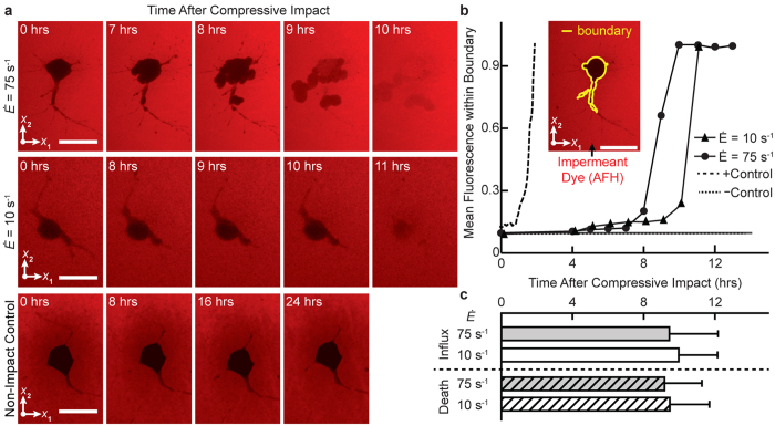
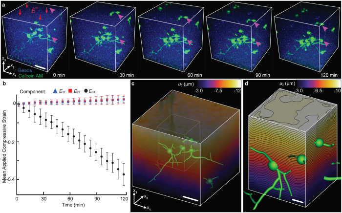
 of 10 s−1 (top) and 75 s−1 (bottom). Scale bar, 20 µm. (b) Mean fluorescence intensity within the cell boundary (inset) for
  (solid triangle),
  (solid circle), a positive control (long dash) with Triton X-100, and a negative control (short dash) without compressive loading. Scale bar, 20 µm. (c) AFH influx time (mean ± standard deviation), or peak rise in internal fluorescence, for
  (solid white; n = 16 cells, N = 5 experiments) and
  (solid gray; n = 23, N = 8), and cellular death time for
  (hatched white; n = 19, N = 8) and
  (hatched gray; n = 22, N = 8). No significant difference was found via t-test comparison.
References
-
- Faul M., Xu L., Wald M. M., Coronado V. & Dellinger A. M. Traumatic brain injury in the United States: national estimates of prevalence and incidence. Inj. Prev. 16, A268 (2010).
-
- Alexander M. P. Mild traumatic brain injury: Pathophysiology, natural history, and clinical management. Neurology 45, 1253–1260 (1995). - PubMed
-
- Inglese M. et al.. Diffuse axonal injury in mild traumatic brain injury: a diffusion tensor imaging study. J. Neurosurg. 103, 298–303 (2005). - PubMed
-
- Scheid R., Walther K., Guthke T., Preul C. & von Cramon D. Y. Cognitive sequelae of diffuse axonal injury. Arch. Neurol. 63, 418 (2006). - PubMed
Publication types
MeSH terms
LinkOut - more resources
Full Text Sources
Other Literature Sources
Medical
