. 2009 Dec 1;114(6):341-58.
doi: 10.6028/jres.114.025. Print 2009 Nov-Dec.

DAVE: A Comprehensive Software Suite for the Reduction, Visualization, and Analysis of Low Energy Neutron Spectroscopic Data

Affiliations

DAVE: A Comprehensive Software Suite for the Reduction, Visualization, and Analysis of Low Energy Neutron Spectroscopic Data

Richard Tumanjong Azuah et al. J Res Natl Inst Stand Technol. .

Abstract

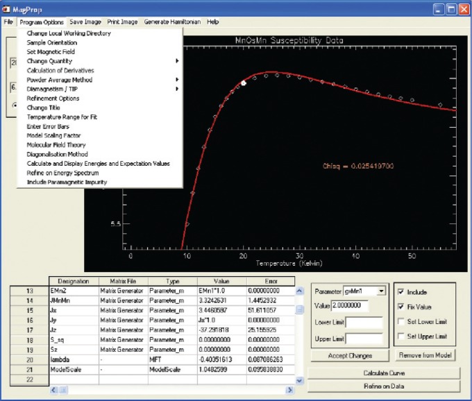
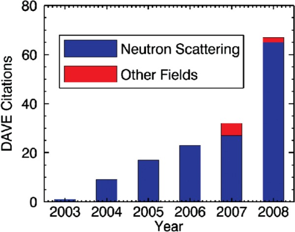
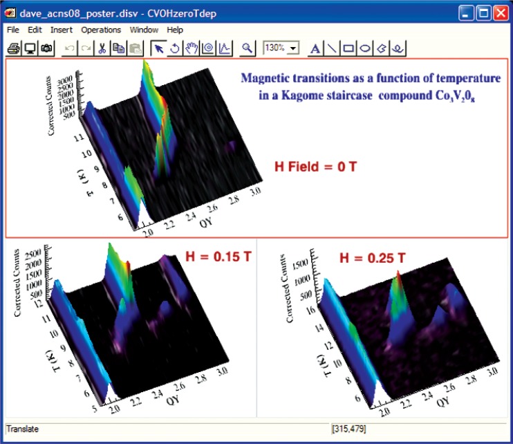
National user facilities such as the NIST Center for Neutron Research (NCNR) require a significant base of software to treat the data produced by their specialized measurement instruments. There is no universally accepted and used data treatment package for the reduction, visualization, and analysis of inelastic neutron scattering data. However, we believe that the software development approach adopted at the NCNR has some key characteristics that have resulted in a successful software package called DAVE (the Data Analysis and Visualization Environment). It is developed using a high level scientific programming language, and it has been widely adopted in the United States and abroad. In this paper we describe the development approach, elements of the DAVE software suite, its usage and impact, and future directions and opportunities for development.

Keywords: analysis; backscattering; inelastic; neutron; reduction; scattering; software; spectrometer; spin echo; time-of-flight; triple-axis; visualization.


Figures

Fig. 1
Fig. 1
An example of TAS Scan Mapper output. Panel A depicts the scattering plane defined by orientation vectors [1,1,0] and [0,0,1]. Black symbols represent a longitudinal elastic scan from (0.02,0.02,1.7) to (0.02,0.02,2.3); the orange, yellow. and blue vectors show the incident and scattered wave vectors and the wave vector transfer, (i.e., ki, kf, and Q), respectively, for the first point of the scan. Unwanted additional scans of wave vector transfers associated with second order scattering off the monochromator and off the analyzer, 2kikf and ki2kf respectively, are shown as sets of yellow and blue symbols, respectively. For clarity, all other wave vector transfers associated with higher order scattering have been omitted. Reciprocal lattice points for the sample and Debye-Scherrer rings associated with powder Bragg reflections from aluminum are shown. Panel B shows a plot of measured intensity versus the z component of Q, labeled L and plotted in reciprocal lattice units. The experimental data are shown as black circles with error bars, and potentially spurious features are highlighted in colors based on their sources. The blue and purple curved connecting arrows relate points in the unwanted scans (as they cross aluminum powder rings) to corresponding features in the data. The feature at L = 2 is a Bragg peak from the sample.
Fig. 2
Fig. 2
Neutron Cross Section table of the elements [16].
Fig. 3
Fig. 3
A plot, obtained using the DCS Experiment Planner, showing the kinematically allowed region bounded by heavy lines representing detectors at 5° and 140° and by solid red vertical lines representing the proposed range of times of flight from the sample to the detectors.
Fig. 4
Fig. 4
Surface view of a 2D data set with the Data Browser. Almost every attribute of the visualization can be customized. The excitation parameters can be determined by fitting the data, using the PAN analysis module.
Fig. 5
Fig. 5
Excitation spectrum of a URu2Si2 single crystal in the H0L plane at T = 1.5 K, where L is integrated from −0.12 to 0.12. Note the minima at the antiferromagnetic zone center (100) and incommensurate positions (1 ± 0.4, 0,0). The feature at (200) is due to phonons. The color bar shows the intensity range [28]. This plot was generated using Mslice from multiple data sets taken at nine different orientations of the sample.
Fig. 6
Fig. 6
Visualization of the Fourier density map (Fobs) and corresponding atomic positions for a simple spinel structure measured by single crystal x-ray diffraction.
Fig. 7
Fig. 7
(Upper) Output from a Gaussian frequency calculation is used to model the predicted vibrational densities of states using the FANS spectrometer with instrumental resolution defined by the monochrornator and collimation conditions. The calculated curve (solid black line) can be compared to real data and empirically adjusted for factors such as background and vibrational overtones. (Lower) Animation and output of the vibrational modes are readily available with the click of a tab button. Relative atomic displacements for the selected eigenvalue are indicated by arrows in static figures.
Fig. 8
Fig. 8
Using PAN to fit tunneling data taken on HFBS. The model function is constructed from a single Gaussian representing the central peak and two Lorentzians representing the inelastic peaks.
Fig. 9
Fig. 9
The main interface of MagProp. The program allows for the visualization and analysis of magnetic data. Experimental (symbols) and fitted (line) magnetization data for a molecular magnet are displayed.
Fig. 10
Fig. 10
The number of citations of the DAVE software since its initial release. The data also show that DAVE has begun to be used in disciplines other than neutron scattering.
Fig. 11
Fig. 11
The visualization interface in DAVE 2 showing a customized window layout and text annotations. The data were taken on BT7 and were reduced using the TAS Data Reduction.

References

    1. The Nobel Prize in Physics 1994. http://nobelprize.org/nobel_prizes/physics/laureates/1994/index.html [Accessed October 8, 2009]
    1. Office of Science and Technology Policy Interagency Working Group on Neutron Science . Report on the Status and Needs of Major Neutron Scattering Facilities and Instruments in the United States. Jun, 2002.
    1. IDL stands for the Interactive Data Language. a product from ITT Visual Information Solutions. http://www.ittvis.com [Accessed October 8, 2009]
    1. DAVE, Data Analysis and Visualization Environment http://www.ncnr.nist.gov/dave [Accessed October 8, 2009]
    1. Squires GL. Introduction to the Theory of Thermal Neutron Scattering. Dover Publications, Inc; 1996.

LinkOut - more resources