

Review
doi: 10.5371/hp.2015.27.3.125.
Epub 2015 Sep 30.
Plain Radiography of the Hip: A Review of Radiographic Techniques and Image Features
Affiliations
- PMID: 27536615
- PMCID: PMC4972716
- DOI: 10.5371/hp.2015.27.3.125
Item in Clipboard
Review
Plain Radiography of the Hip: A Review of Radiographic Techniques and Image Features
Hip Pelvis.
2015 Sep.
Abstract
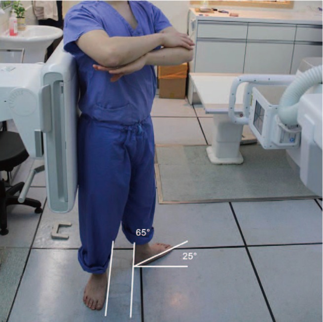
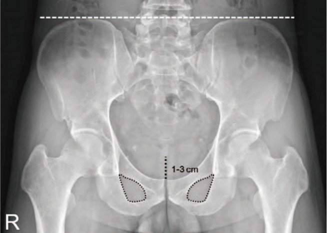
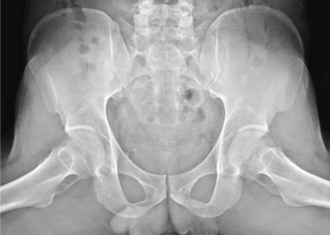
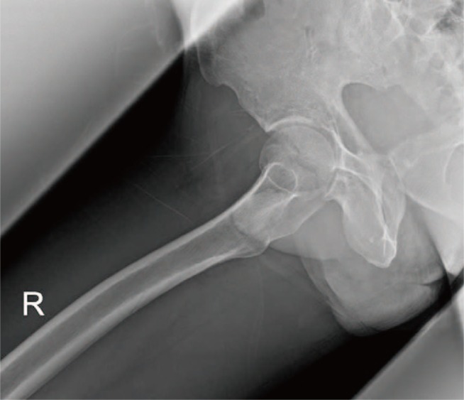
Plain radiographic examination is a fundamental approach to the diagnosis and treatment decision-making of the hip. A thorough understanding of standard radiographic techniques, radiographic anatomy, and disease patterns affecting the hip can be helpful in improving diagnostic accuracy. This article reviews the standard protocols used to obtain radiographic projections of the hip and addresses specific signs and various radiographic measurements used to adequately and reliably recognize structural diseases of the hip.
Keywords: Evaluation; Hip; Radiography; Technique.
Figures
Similar articles
-
Revisiting the Anteroinferior Iliac Spine: Is the Subspine Pathologic? A Clinical and Radiographic Evaluation.Clin Orthop Relat Res. 2018 Jul;476(7):1494-1502. doi: 10.1097/01.blo.0000533626.25502.e1. Clin Orthop Relat Res. 2018. PMID: 29794857 Free PMC article.
-
A comparison of radiographic and scintigraphic techniques to assess aseptic loosening of the acetabular component in a total hip replacement.J Bone Joint Surg Am. 2004 Nov;86(11):2456-63. doi: 10.2106/00004623-200411000-00015. J Bone Joint Surg Am. 2004. PMID: 15523018
-
Which Two-dimensional Radiographic Measurements of Cam Femoroacetabular Impingement Best Describe the Three-dimensional Shape of the Proximal Femur?Clin Orthop Relat Res. 2019 Jan;477(1):242-253. doi: 10.1097/CORR.0000000000000462. Clin Orthop Relat Res. 2019. PMID: 30179924 Free PMC article.
-
The use of plain radiography, subtraction arthrography, nuclear arthrography, and bone scintigraphy in the diagnosis of a loose acetabular component of a total hip prosthesis: a systematic review.J Arthroplasty. 2007 Sep;22(6):818-27. doi: 10.1016/j.arth.2006.08.004. Epub 2007 Mar 28. J Arthroplasty. 2007. PMID: 17826271
-
[Radiological examination of the hip. Analysis of standard projections].Orthopade. 2006 Jan;35(1):16-21. doi: 10.1007/s00132-005-0889-3. Orthopade. 2006. PMID: 16322974 Review. German.
Cited by
-
Logistic Regression Analysis of Risk Factors and Improvement of Clinical Treatment of Traumatic Arthritis after Total Hip Arthroplasty (THA) in the Treatment of Acetabular Fractures.Comput Math Methods Med. 2022 May 4;2022:7891007. doi: 10.1155/2022/7891007. eCollection 2022. Comput Math Methods Med. 2022. Retraction in: Comput Math Methods Med. 2023 Jul 19;2023:9819065. doi: 10.1155/2023/9819065. PMID: 35572823 Free PMC article. Retracted.
-
Hip Osteoarthritis-Clinical-Statistical Study and Surgical Treatment.Curr Health Sci J. 2024 Apr-Jun;50(2):246-255. doi: 10.12865/CHSJ.50.02.10. Epub 2024 Jun 30. Curr Health Sci J. 2024. PMID: 39371067 Free PMC article.
-
Artificial intelligence (AI) vs. human in hip fracture detection.Heliyon. 2022 Oct 27;8(11):e11266. doi: 10.1016/j.heliyon.2022.e11266. eCollection 2022 Nov. Heliyon. 2022. PMID: 36339768 Free PMC article.
-
An Online Learning Tool to Obtain, Optimize, and Interpret Radiographs During Total Hip Arthroplasty.Hawaii J Health Soc Welf. 2022 Mar;81(3 Suppl 1):37-44. Hawaii J Health Soc Welf. 2022. PMID: 35340938 Free PMC article.
-
Posterior Protrusion Measures (PPM) as an Innovative Index in Classifying Plain Lateral Radiograph Images of Pertrochanteric Fracture Using the Revised AO Foundation/Orthopaedic Trauma Association (AO/OTA) Classification.Cureus. 2022 Dec 24;14(12):e32898. doi: 10.7759/cureus.32898. eCollection 2022 Dec. Cureus. 2022. PMID: 36699794 Free PMC article.
References
-
- Callaghan JJ, Rosenberg AG, Rubash HE. The adult hip. 2nd ed. Philadelphia: Lippincott Williams & Wilkins; 2007. pp. 349–391.
-
- Tannast M, Zheng G, Anderegg C, et al. Tilt and rotation correction of acetabular version on pelvic radiographs. Clin Orthop Relat Res. 2005;438:182–190. - PubMed
-
- Hananouchi T, Sugano N, Nakamura N, et al. Preoperative templating of femoral components on plain X-rays Rotational evaluation with synthetic X-rays on ORTHODOC. Arch Orthop Trauma Surg. 2007;127:381–385. - PubMed
-
- Engesæter IØ, Laborie LB, Lehmann TG, et al. Radiological findings for hip dysplasia at skeletal maturity. Validation of digital and manual measurement techniques. Skeletal Radiol. 2012;41:775–785. - PubMed
Publication types
LinkOut - more resources
Full Text Sources
Other Literature Sources
