. 2016 Aug 19:6:31689.
doi: 10.1038/srep31689.

Live volumetric (4D) visualization and guidance of in vivo human ophthalmic surgery with intraoperative optical coherence tomography

Affiliations

Live volumetric (4D) visualization and guidance of in vivo human ophthalmic surgery with intraoperative optical coherence tomography

O M Carrasco-Zevallos et al. Sci Rep. .

Abstract

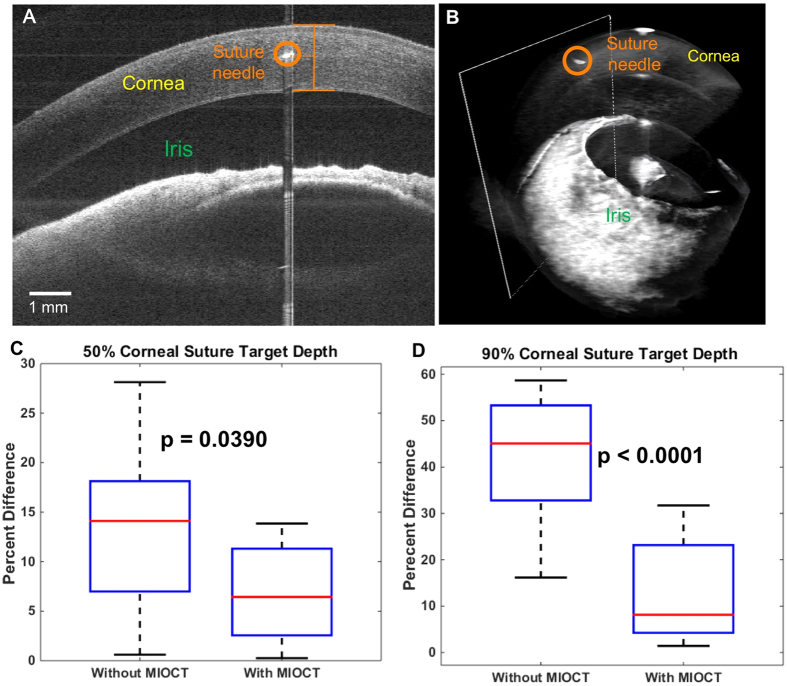
Minimally-invasive microsurgery has resulted in improved outcomes for patients. However, operating through a microscope limits depth perception and fixes the visual perspective, which result in a steep learning curve to achieve microsurgical proficiency. We introduce a surgical imaging system employing four-dimensional (live volumetric imaging through time) microscope-integrated optical coherence tomography (4D MIOCT) capable of imaging at up to 10 volumes per second to visualize human microsurgery. A custom stereoscopic heads-up display provides real-time interactive volumetric feedback to the surgeon. We report that 4D MIOCT enhanced suturing accuracy and control of instrument positioning in mock surgical trials involving 17 ophthalmic surgeons. Additionally, 4D MIOCT imaging was performed in 48 human eye surgeries and was demonstrated to successfully visualize the pathology of interest in concordance with preoperative diagnosis in 93% of retinal surgeries and the surgical site of interest in 100% of anterior segment surgeries. In vivo 4D MIOCT imaging revealed sub-surface pathologic structures and instrument-induced lesions that were invisible through the operating microscope during standard surgical maneuvers. In select cases, 4D MIOCT guidance was necessary to resolve such lesions and prevent post-operative complications. Our novel surgical visualization platform achieves surgeon-interactive 4D visualization of live surgery which could expand the surgeon's capabilities.


Conflict of interest statement

At the time this study was conducted, Dr. Izatt was Chairman and Chief Scientific Advisor for Bioptigen, Inc. (since acquired by Leica Microsystems) and had corporate, equity, and intellectual property interests (including royalties) in this company. O.M.C.Z., B.K., C.V., L.S., S.F., A.N.K., C.A.T. and J.A.T. are inventors on issued and pending patents pertaining to the technology described in this paper.

Figures

Figure 1
Figure 1. Integrated 4D MIOCT system and real-time feedback to the surgeon.
(A) Photograph of the 4D MIOCT system portable cart that housed the OCT laser, interferometer, electronics, and processing computer. (B) Photograph of MIOCT scanner, operating microscope, and heads-up display (HUD). The HUD and MIOCT scanner integrated seamlessly into microscope. (C) Photograph of system in use during human surgery. The microscope-integrated design enabled OCT data acquisition during live surgery. (D) 4D MIOCT acquisition with the scan (green box) oriented to the axis of the surgical instrument. The MIOCT scan axis could be arbitrarily rotated and shifted laterally to scan the surgical site of interest. (E) Rotationally-offset stereo MIOCT volumes and B-scans rendered in real time. (F) Projection of the 4D MIOCT data and other supporting surgical data into the oculars for real-time OCT feedback to the surgeon.
Figure 2
Figure 2. Translation of prototype 4D MIOCT system from ex vivo studies to human microsurgeries.
(A) Preliminary studies were performed to evaluate 4D MIOCT performance, visualization of microsurgical instruments, and feedback to the surgeon using the HUD. (B) 4D MIOCT-guided surgical maneuvers were quantitatively evaluated in mock surgical trials involving 17 surgeons and surgeons-in-training. (C,D) The utility of in vivo 4D MIOCT imaging was evaluated in 13 human anterior eye surgeries (C) and 35 human retinal surgeries (D).
Figure 3
Figure 3. 4D MIOCT increases suture placement accuracy in mock surgical trials.
A group of 14 surgeons-in-training were asked to perform corneal suture passes at two target depths with and without 4D MIOCT guidance during simulated surgery in cadaveric porcine eyes. (A) Representative B-scan located at the point of maximal needle depth. The needle, cornea, and iris are labeled in orange, yellow, and green, respectively. (B) Corresponding volumetric image. The B-scan (A) location is denoted by white rectangle. In this trial, the surgeon inserted the suture needle at a 44% corneal depth, 6% away from the 50% target depth. The cross-sectional view allowed accurate grading of the suture needle placement within corneal tissue. (C,D) Box plots summarizing suture placement with and without MIOCT guidance for 50% (C) and 90% (D) target depths, respectively. The data is plotted in percent difference from the target depth; closer to 0% difference is more accurate. At both target depths, the surgeons achieved increased suture placement accuracy with MIOCT.
Figure 4
Figure 4. 4D MIOCT improves the control of instrument placement relative to tissue in mock surgical trials.
Three ophthalmic surgeons were asked to place their instrument as close to retina as possible without contacting tissue during simulated porcine eye retinal surgery. Each surgeon performed the maneuver 8 times with and without 4D MIOCT guidance. (A) Porcine retina as viewed through the operating microscope. The green dashed box denotes the 5 × 5 mm MIOCT lateral field of view. (B) B-scan located at the point of the instrument’s closest proximity to the retinal surface. The instrument and retina are labeled in red and yellow, respectively. The cross-sectional view allowed accurate grading of the instrument/retina distance. (C) Corresponding volumetric image with the B-scans (B) location denoted by the white rectangle. In this trial, the surgeon placed the instrument 214 μm above the retinal surface. (DF) Box plots summarizing instrument placement relative to the retinal surface with and without MIOCT guidance for all 3 ophthalmic surgeon participating in the study. Improved visual feedback with MIOCT guidance allowed each surgeon to place their instrument closer to the retinal surface (closer to zero without contacting) than without MIOCT guidance.
Figure 5
Figure 5. 4D MIOCT reveals previously unidentified volumetric tissue deformation during human retinal brushing.
4D MIOCT was performed during retinal brushing to initiate peeling of a pathologic membrane in human retinal surgery. (A) Excerpts from a 4D MIOCT recording showing retinal brushing with a diamond dusted membrane scraper (DDMS) (purple) around a macular hole (MH) (blue) (Movie S1). The corresponding frames from the surgical camera used to record the view through the operating microscope are shown above the MIOCT data. The macular hole is more readily identifiable in the MIOCT volumes. In addition, volumetric retinal deformation during the brushing maneuver and residual retinal deformation (RRD) (red) after the maneuver was only visible in the MIOCT data. (B) Excerpts from a 4D MIOCT illustrating retinal brushing with a microsurgical flex loop (FL) (yellow) and elevated blood vessels (BV) (black) (Movie S2). Compared to (A), the flex loop is less abrasive and results in less overall retinal deformation and no residual deformation. The volumetric frames rates for (A,B) were 3.33 and 5.0 volumes/second, respectively. Time stamps are in seconds (yellow numbers). The green dashed box denotes the lateral MIOCT field of view. The volumetric MIOCT field of view was 3 × 5 × 5 mm.
Figure 6
Figure 6. 4D MIOCT enhanced visualization during removal of human pathologic translucent membranes.
4D MIOCT was performed during peeling of epiretinal membranes (ERM) in human retinal surgery. (A) Excerpts of a 4D MIOCT recording illustrating grasping and peeling of an ERM (red) with surgical intraocular forceps (IF) (purple) (Movie S3). The maneuver is visualized in the surgical camera frames (top row) and volumes (bottom row). The ERM flap used to initiate the peeling is more readily identifiable in the MIOCT data. Additionally, the angle and membrane tension during the ERM peel are more appreciable in the MIOCT images. (BE) show the camera frame (B), B-scan (C), and volumetric renderings (D,E) of ERM (red) around a macular hole (MH) (blue) before peeling in a separate surgery. The exact axial proximity of the ERM to underlying healthy retina is only directly visible in the B-scan (C) and volumes (D,E). The complex 3D ERM microarchitecture could be inspected in volumetric MIOCT data from different perspectives (D,E). (FI) shows similar views of the macula after ERM peeling. The volumetric frame rate was 3.33 volumes/second. Time stamps are in seconds (yellow). The green dashed box denotes the lateral MIOCT field of view. The volumetric MIOCT field of view was 3 × 5 × 5 mm.
Figure 7
Figure 7. 4D MIOCT-guided identification and resolution of abnormal adhesion of iris to the graft/cornea interface during a human corneal transplantation.
4D MIOCT guidance was necessary to treat the lesion the lesion since it could not be visualized top-down through the operating microscope. (A–C) show the microscope view (A), B-scan (B), and volume (C) at the time during which the surgeon identified the abnormal iris adhesion (IA) to cornea/graft interface (red) in the MIOCT data. The white rectangle in the volume denotes the location of the B-scan. (D) Excerpts of 4D MIOCT recording during treatment of the lesion (Movie S4). Using 4D MIOCT for localization guidance, the surgeon was able to direct a cannula (CA) (blue) and inject viscoelastic between the iris and corneal graft to release the adhesion. Further evaluation using MIOCT revealed resolution of the adhered iris with clear intervening space between iris and cornea. The volumetric rate for (D) was 0.5 volumes/second. Time stamps (yellow) are in seconds. The green dashed box denotes the lateral MIOCT field of view. The volumetric MIOCT field of view was 6 × 10 × 10 mm.
Figure 8
Figure 8. 4D MIOCT-guided unfolding of graft below native cornea during human partial thickness corneal transplantation.
4D MIOCT imaging was necessary to determine the axial distance between the graft and native cornea, which was invisible through the operating microscope. (A) Frames from the surgical camera (top) and excerpts from a 4D MIOCT recording shown in B-scans (middle) and volumes (bottom) during graft insertion and unfolding (Movie S5). As the graft (GR) (blue) unfolded, the surgeon used 4D MIOCT data to monitor the graft/cornea interface (GCI) (orange) and to ensure graft/cornea apposition. The volumetric rate for was 0.5 volumes/second. An image artifact due to specular reflection (SR) (yellow) from the corneal apex is present in the middle of the volumes. Time stamps (black) are in seconds. The white rectangle in the volumes denotes the location of the B-scan. The green dashed box denotes the lateral MIOCT field of view. The volumetric MIOCT field of view was 6 × 10 × 10 mm.

Similar articles

Cited by

References

    1. Daniel R. K. Microsurgery: Through the looking glass. N. Engl. J. Med. 300, 1251–1257 (1979). - PubMed
    1. Singh M. & Saxena A. Microsurgery: A Useful and Versatile Tool in Surgical Field. Surg. Curr. Res. 04, 9–11 (2014).
    1. Reznick R. K. & MacRae H. Teaching Surgical Skills - Changes in the Wind. N. Engl. J. Med. 355, 2664–9 (2006). - PubMed
    1. Ramachandran S., Ghanem A. M. & Myers S. R. Assessment of microsurgery competency-where are we now? Microsurgery 33, 406–415 (2013). - PubMed
    1. Institute N. E. Age-related Eye Disease Study. (2013).

Publication types

MeSH terms