. 2016 Aug 25;11(8):e0161490.
doi: 10.1371/journal.pone.0161490. eCollection 2016.

Frugal Droplet Microfluidics Using Consumer Opto-Electronics

Affiliations

Frugal Droplet Microfluidics Using Consumer Opto-Electronics

Caroline Frot et al. PLoS One. .

Abstract

The maker movement has shown how off-the-shelf devices can be combined to perform operations that, until recently, required expensive specialized equipment. Applying this philosophy to microfluidic devices can play a fundamental role in disseminating these technologies outside specialist labs and into industrial use. Here we show how nanoliter droplets can be manipulated using a commercial DVD writer, interfaced with an Arduino electronic controller. We couple the optical setup with a droplet generation and manipulation device based on the "confinement gradients" approach. This device uses regions of different depths to generate and transport the droplets, which further simplifies the operation and reduces the need for precise flow control. The use of robust consumer electronics, combined with open source hardware, leads to a great reduction in the price of the device, as well as its footprint, without reducing its performance compared with the laboratory setup.


Conflict of interest statement

CNB is an inventor on three patents, owned by Ecole Polytechnique and the CNRS, that are related to different aspects of this work: WO 2006/018490 \Microuidic circuit with an active component". WO 2011/038475 \Microuidic circuit". WO 2011/121220 \Device for forming drops in a microuidic circuit". This does not alter the authors’ adherence to PLOS ONE policies on sharing data and materials.

Figures
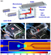
Fig 1
Fig 1. Coupling the microfluidics and the DVD writer.
(a) Schematic of the microfluidic device on top of the DVD writer. The DVD focus and tracking positions are controlled through an Arduino card, which also controls the on-off switching of the laser. (b-c) Images of the DVD writer, without and with the microfluidic device in place. (d) 3D profilometry of the microfluidic circuit. The colors indicate the local channel depth, as shown on the color bar. The left-most entrance transports the continuous oil phase. The entrance on the right side is used to inject the water phase. The sloped region produces monodisperse drops passively. finally, a default central rail and four side rails are visible on the right side of the image.
Fig 2
Fig 2. Controlling the DVD laser and lens.
The DVD laser was controlled using a constant current source. The power output of the circuit was determined manually by turning the variable resistor. The mobile lens position was controlled through the Arduino motor shield. Its position could be programmed through software. Extreme care must be taken while manipulating the laser, as these are relatively high power lasers that can cause severe eye damage.
Fig 3
Fig 3. Calibration of laser forcing.
(a) Position of the laser spot as a function of the command on the Arduino board, in the quasi-static regime. (b-e) Dynamic traces of the laser position as a function of time filmed through high speed camera. The laser was displaced over a distance of 1.05 mm with a duration of (b) 500 ms, (c) 100 ms, (d) 50 ms, and (e) 20 ms.
Fig 4
Fig 4. Drop size and velocity.
(a) Value of the water inlet pressure that allows a constant droplet size, as a function of the imposed pressure on the oil inlet. (b) Velocity of the droplets, downstream of the sloped region, as a function of the imposed pressure on the oil inlet.
Fig 5
Fig 5. Required power for derailing drops.
Minimum electrical current required to derail droplets onto the first rail. Faster moving droplets require a more intense laser to switch rails. The largest current achieved on this laser was 0.28 A. Drops beyond a velocity of 6 mm/s could not be derailed at this maximum value.
Fig 6
Fig 6. Multiple sorting positions.
Sorting droplets onto different rails by controlling the position of the laser lens. Each panel shows a superposition of images for a single drop in the device. (a) If the laser is off, the drop remains on the default central rail. (b-d) Different laser positions force the drop to jump on different rails, which lead to different regions downstream.

References

    1. Lai S, Wang S, Luo J, Lee LJ, Yang ST, Madou MJ. Design of a compact disk-like microfluidic platform for enzyme-linked immunosorbent assay. Analytical chemistry. 2004;76(7):1832–1837. 10.1021/ac0348322 - DOI - PubMed
    1. Hadwen B, Broder G, Morganti D, Jacobs A, Brown C, Hector J, et al. Programmable large area digital microfluidic array with integrated droplet sensing for bioassays. Lab on a Chip. 2012;12(18):3305–3313. 10.1039/c2lc40273d - DOI - PubMed
    1. Niu X, Gulati S, Edel JB, deMello AJ. Pillar-induced droplet merging in microfluidic circuits. Lab Chip. 2008;8(11):1837–1841. 10.1039/b813325e - DOI - PubMed
    1. Huebner A, Bratton D, Whyte G, Yang M, deMello AJ, Abell C, et al. Static microdroplet arrays: a microfluidic device for droplet trapping, incubation and release for enzymatic and cell-based assays. Lab Chip. 2009;9(5):692–698. 10.1039/B813709A - DOI - PubMed
    1. Zagnoni M, Cooper JM. A microdroplet-based shift register. Lab Chip. 2010;10(22):3069–3073. 10.1039/c0lc00219d - DOI - PubMed

LinkOut - more resources