. 2016 Aug 26:6:32300.
doi: 10.1038/srep32300.

Directional Reflective Surface Formed via Gradient-Impeding Acoustic Meta-Surfaces

Affiliations

Directional Reflective Surface Formed via Gradient-Impeding Acoustic Meta-Surfaces

Kyungjun Song et al. Sci Rep. .

Abstract

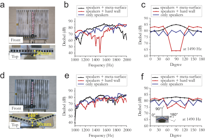
Artificially designed acoustic meta-surfaces have the ability to manipulate sound energy to an extraordinary extent. Here, we report on a new type of directional reflective surface consisting of an array of sub-wavelength Helmholtz resonators with varying internal coiled path lengths, which induce a reflection phase gradient along a planar acoustic meta-surface. The acoustically reshaped reflective surface created by the gradient-impeding meta-surface yields a distinct focal line similar to a parabolic cylinder antenna, and is used for directive sound beamforming. Focused beam steering can be also obtained by repositioning the source (or receiver) off axis, i.e., displaced from the focal line. Besides flat reflective surfaces, complex surfaces such as convex or conformal shapes may be used for sound beamforming, thus facilitating easy application in sound reinforcement systems. Therefore, directional reflective surfaces have promising applications in fields such as acoustic imaging, sonic weaponry, and underwater communication.


Figures

Figure 1
Figure 1. Basic design concept for planar-type sound antenna with curved reflection phase Φ(x).
(a) Conceptual figures of planar directional surface with symmetric phase gradient dΦ(x)/dx with respect to the origin. Such surfaces can be obtained using space elements with varying degrees of coiling positioned along the planar surface. The surface can then be used to form a distinct focal line located directly above and at a distance f from the origin, as shown in the figure. The structure is invariant in the z direction. (b) Conceptual schematic of parabolic antenna, having an identical focal line to the planar meta-surface.
Figure 2
Figure 2. Directive sound antenna design based on acoustic metamaterials mimicking parabolic cylindrical antenna.
(a) Schematic of acoustic meta-surface consisting of array of Helmholtz resonators with varying coiled path lengths, p (Sample 1, number of resonators on each side, N = 8). The subwavelength width, s, subwavelength separation, d, gap, g, and total length, D, are fixed to 15, 20, 2 and 317.5 mm, respectively, while p is adjusted to 1, 5.5, 9, 12.5, 16.5, 24, 31, and 36 mm. The structure is invariant in the z direction. (b) Series LC circuit model for resonators comprising the meta-surface, which have minimum impedance for the reflection phase, Φ(x) = π, at the resonance frequency. (c) Calculated Φ(x) for resonators having varying p, which comprise the meta-surface. (d) Calculated Φ(x) profile for meta-surface at various incident sound frequencies. (e) Calculated parabolic profile of Φ(x) at 1490 Hz. The profile follows the relationshipformula image
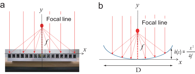
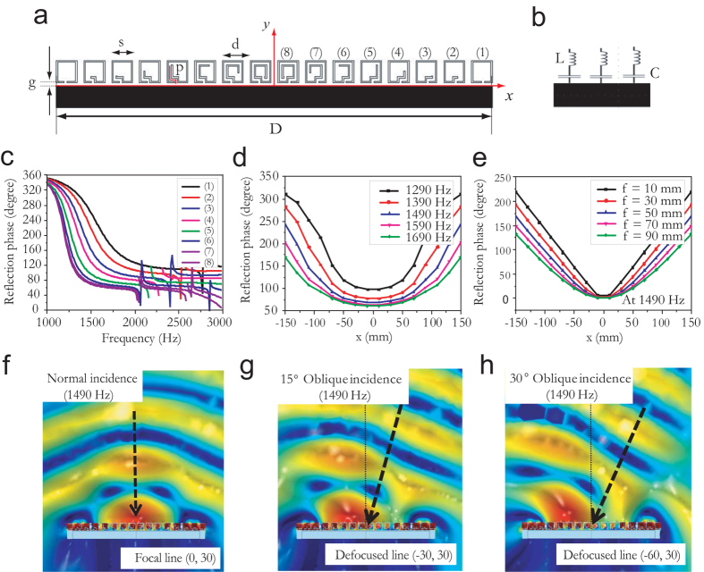
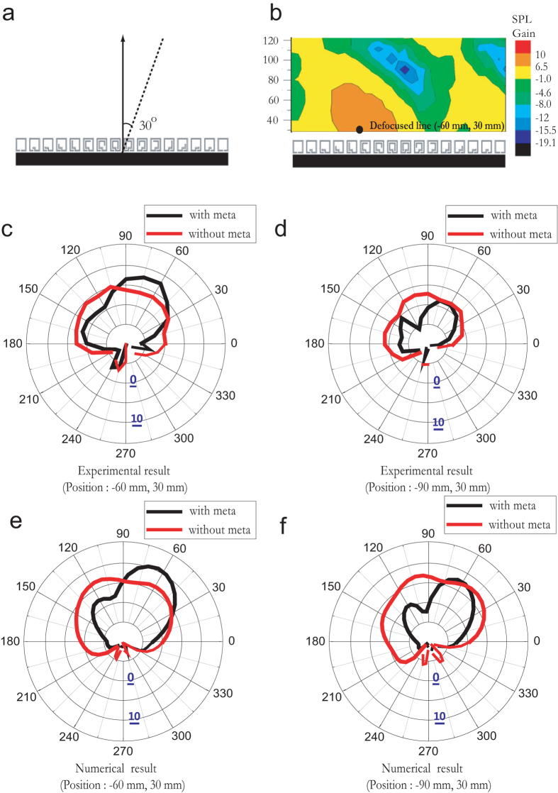
, where λ is the wavelength and f is the focal length. (fh) Sound pressure level profiles for normally, 15° obliquely, and 30° obliquely incident plane waves at 1490 Hz resulting in focal line at approximately (0, 30) and defocused lines at approximately (−30, 30) and (−60, 30), respectively. (All positions are in millimetres).
Figure 3
Figure 3. Acoustic antenna in receiving mode based on artificial textured meta-surface mimicking parabolic-cylinder antenna.
(a) Photograph of prototype meta-surface Sample 1 with subwavelength separation d = 20 mm. (b) Measured SPL gain contour near acoustic meta-surface located 1.5 m from source speaker with 1490 Hz pure tone. (c) Calculated and (d) measured sound pressure level (SPL) gain at (0, 30) from 1000 to 2000 Hz for normally incident sound wave. (e,f) Calculated (line) and measured (dot) polar SPL gain at (0, 30) and (0, 100) for 1490 Hz incident frequency, respectively. (All positions are in millimetres).
Figure 4
Figure 4. Received beamforming achieved by manipulating the number of acoustic resonators on each side of the acoustic meta-surface, N.
(a) Calculated and (b) measured polar sound pressure level (SPL) gain for Samples 1–3, having N = 8 (Sample 1), 6 (Sample 2) and 4 (Sample 3), with 1490 Hz incident sound frequency.
Figure 5
Figure 5. Received beamforming measured by microphone located at off-axis and displaced from focal-line.
(a) Schematic of experimental setup used to measure sound pressure level (SPL) gain for 30° obliquely incident sound wave at 1490 Hz. (b) SPL gain contour for 30° obliquely incident sound wave. Measured polar SPL gain for setup shown in (a) at (c) (−60, 30) and (d) (−90, 30). Calculated polar SPL gain for setup shown in (a) at positions (e) (−60, 30) and (f) (−90, 30). (All positions are in millimetres).
Figure 6
Figure 6. Directive sound antenna in transmitting mode.
(a) Prototype of flat reflective meta-surface (Sample 1) with phase array feeds consisting of 13 point-like sources. (b) Measured microphone sound pressure levels (SPLs) at the normal direction of a plane, which are located 1 m from speakers with a flat reflective surface, a hard-wall reflective surface, and no structure. (c) Measured polar SPL for flat surfaces with 1490 Hz speakers. (d) Prototype of convex reflective meta-surface Sample 1 with 140° exterior angle and phase array feeds consisting of 13 point-like sources. (e) Measured microphone SPLs at the normal direction of a plane, which are located 1 m from sources with a convex reflective meta-surface, convex hard-wall reflective surface, and no structure. (f) Measured polar SPL for convex surfaces with 1490 Hz speakers. Inset: The x′ axis indicates the direction with tilt angle α relative to the x-axis.

References

    1. Blackstock D. T. Fundamentals of physical acoustics. John Wiley & Sons (2000).
    1. Wade G. Acoustic imaging: cameras, microscopes, phased arrays, and holographic systems. Springer Science & Business Media (2013).
    1. Westervelt P. J. Parametric Acoustic Array. J. Acoust. Soc. Am. 35, 535–537 (1963).
    1. Bellin J. L. S. & Beyer R. T. Experimental Investigation of an End‐Fire Array. J. Acoust. Soc. Am. 34, 1051–1054 (1962).
    1. Kinsler L. E., Frey A. R., Coppens A. B. & Sanders J. V. Fundamentals of Acoustics (Wiley, New York, 1999).

Publication types