. 2017 Sep 1;27(9):4463-4477.
doi: 10.1093/cercor/bhw248.

Three-Dimensional Digital Template Atlas of the Macaque Brain

Affiliations

Three-Dimensional Digital Template Atlas of the Macaque Brain

Colin Reveley et al. Cereb Cortex. .

Abstract

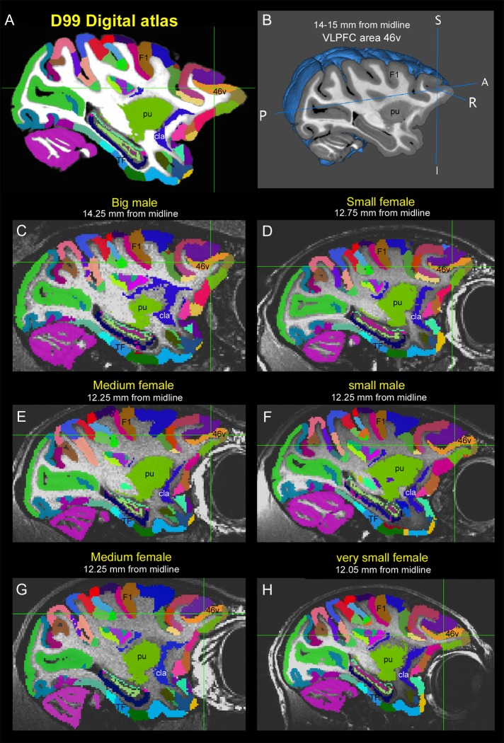
We present a new 3D template atlas of the anatomical subdivisions of the macaque brain, which is based on and aligned to the magnetic resonance imaging (MRI) data set and histological sections of the Saleem and Logothetis atlas. We describe the creation and validation of the atlas that, when registered with macaque structural or functional MRI scans, provides a straightforward means to estimate the boundaries between architectonic areas, either in a 3D volume with different planes of sections, or on an inflated brain surface (cortical flat map). As such, this new template atlas is intended for use as a reference standard for macaque brain research. Atlases and templates are available as both volumes and surfaces in standard NIFTI and GIFTI formats.

Keywords: 3D digital atlas; AFNI and SUMA; anatomical templates; architectonic areas; macaque monkey.


Figures

Figure 1.
Figure 1.
Original 2D atlas and MRI data of rhesus macaque brain. (A) An example of 2D sagittal slice with delineated cortical and subcortical areas, obtained from sagittal data set of thirty 1-mm interval sections in Saleem and Logothetis (2012) atlas. The corresponding in vivo MRI slice, and the abbreviation list of delineated areas in the sagittal section is also shown on the left. The dorsal view of the rendered brain image on the top right indicates the mediolateral location of this sagittal slice, which is located 7 mm lateral from the midline. (B) Examples of vectorized atlas sections. The 30 sagittal sections were then converted into vectorized images with each region marked as filled polygon of a different color using Canvas program (.cvx file format). These 30 slices were stacked and created 3D volume of the brain using “surrogate D99 brain”, aligned to original MRI data set, and sequence of manual and automated processing steps as shown in Figures 2 and 3.
Figure 2.
Figure 2.
Ex vivo surrogate anatomical volume. The structural image of another monkey (DB58 T1) with high spatial resolution (250 µm isotropic) was obtained ex vivo using magnetizable transfer ratio sequence (B), and was nonlinearly registered to the original T1 D99 from the Saleem and Logothetis atlas (A). We used this newly transformed volume (Surrogate D99); (C) for atlas reconstruction as shown in Figure 3. Note the correspondence of sulci and gyri in both original D99 and Surrogate D99 (white arrows in A and C) but see different sulcal patterns in DB58 T1 (gray arrows in B).
Figure 3.
Figure 3.
Creation of the 3D digital template atlas from 2D atlas sections. (A) 3D volume of the brain with delineation of cortical areas, created from 30 colored sagittal images. Note the rasterized or coarse appearance of section in other (coronal) plane of sections. (B) The coarse map of the areal boundaries was registered with the surrogate volume using affine transformation and nonlinear adjustments. Note that the color labels were jagged and not restricted to the gray matter boundaries (see arrows). (C) Interpolation of colored maps within the gray matter mask, obtained from high-resolution surrogate MRI volume. Note the complete labeling of gray matter with no intrusion into adjacent white matter regions (see arrows) but some labels did not adequately match the known anatomical boundaries. (D) Assignment of cortical boundaries based on radial paths (see the methods for more detail). (E, F) The labeled surrogate brain with complete labeling of region restricted to the cortex, with clear, radial divisions between neighboring cortical areas (compare final map in F with the initial rasterized map in A). Following the construction of atlas as shown in A–F, the 3D data set was integrated into Analysis of Functional NeuroImages (AFNI) and SUMA interface (see Fig. 4), where the manual correction of areal extent and architectonic borders of different regions were done in comparison with the original sections from Saleem and Logothetis atlas.
Figure 4.
Figure 4.
3D digital template atlas in AFNI and SUMA interface. Areal delineations of different cortical and subcortical areas in sagittal, horizontal, and coronal planes of sections (AC), and on the 3D brain surface (D), which is based on the Saleem and Logothetis atlas (E), displayed in AFNI/SUMA window. The 2 different stereotaxic coordinates of current location (cross hairs; e.g., area 45a), one with reference to anterior commissure (AC), and other with reference to ear bar zero (EBZ) in Saleem and Logothetis atlas are also indicated in AFNI “whereami” window (see “Focus point” in F).
Figure 5.
Figure 5.
Registration of 3D atlas to various test subjects. Here D99 digital template atlas is registered with T1 MRI images of 6 individual brains of different age groups using a novel-processing pipeline developed within AFNI and SUMA (see the text). (A) One of the sagittal slices from D99 digital atlas (+14 or +15 mm from the midline) with delineated cortical and subcortical areas. (B) The corresponding slice on the D99 rendered brain with MRI (created in software Mango). (CH) sagittal slices from 6 animals, with the D99 atlas registered to the MRI images of each animal in its own native space. Note the corresponding location of ventrolateral prefrontal region in the ventral bank of principal sulcus (area 46 v; cross hair) in D99 digital atlas and 6 other animals. Abbreviations: 46 v, ventrolateral prefrontal area; cla, claustrum; F1, agranular frontal area F1 (or area 4); pu, putamen; TF, area TF of the parahippocampal cortex.
Figure 6.
Figure 6.
Comparison of architectonic areas in the registered MRI volumes with the corresponding sections in Saleem and Logothetis (2012) atlas. (A, B) The coronal slices with delineated cortical and subcortical areas in subject MQ registered to digital atlas (D99) and digital atlas registered to subject MQ, respectively. The coronal section in B is the same section as shown in Figure 7F, which is digitally rotated in the dorsoventral plane around the mediolateral axis to match with the corresponding histology section from the same case illustrated in Figure 7J. (C) Corresponding section drawing of the right hemisphere with delineated areas from Saleem and Logothetis atlas (see their Fig. 85, p. 201). This slice is located 13 mm anterior to the EBZ. Note that as expected, the labeled regions in A, where the subject MQ is registered to digital atlas (to its original native space) closely matched with regions in Saleem and Logothetis atlas (compare the cortical and subcortical areas in A and C). As noted above, the registered volume in B is slightly rotated to match with the corresponding histology section (see Fig. 7). This resulted in few mismatched cortical areas at the border between anterior and posterior cingulate gyrus (areas 23 and 24’) dorsally, and anterior and posterior TE in the inferotemporal cortex (areas TEad and TEpd) ventrally (compare red stars in A and B). See the result section for more detail.
Figure 7.
Figure 7.
Registration of 3D atlas to different test subjects with histological confirmation of architectonic areas. In this example, the D99 digital template atlas is also registered with T1 MRI volume of 2 individual brains that are different from the cases shown in Figure 5. (AD) Selected coronal slices from in vivo T1 weighted MRI volume of cases MQ and BASS. (EH) Digital atlas (D99) registered and overlaid on the MQ and BASS MRI volumes (same coronal slices as shown in A–D). (IL) Corresponding histology sections of the left hemisphere in MQ and BASS (green rectangular boxes in A–D) stained immunohistochemically for the neurofilament protein, recognized by SMI-32 antibody (I–K), and Nissl staining (L). We digitally rotated both MRI and registered volumes to match with histology sections. Note the correspondence of sulci and gyri in both MRI/registered volume and histology sections. We also confirmed the spatial location and architectonic features of the selected cortical and subcortical areas in the registered slices (arrows in E–H; small boxes in first and third columns) with the corresponding histology sections as illustrated in M–T. (MR) High-power photomicrographs showing the differential distribution of SMI-32 positive pyramidal neurons in the auditory (A1, RM), medial temporal lobe (entorhinal cortex (EC), CA1), dorsal temporal pole (TGdd), and subcortical (subthalamic nucleus (STN), substantia nigra (SN), and mammillary bodies (MB)) areas. We also confirmed the spatial location, and architectonic features of auditory areas in case MQ (e.g., primary auditory area A1 and medial belt area RM) with reference to our previous study (see Scott et al. 2015, their Fig. 3F, I, Q). (ST) High-power photomicrographs showing the architectonic features of the CA1 region of hippocampus, EC, and adjacent areas in the Nissl stained section.
Figure 8.
Figure 8.
Mapping fMRI results onto the digital atlas. (A) fMRI activation from a subject depicting the location of regions responsive to faces greater than scrambled faces. Activity is displayed over the subject's high-resolution anatomical images and thresholded at t > 10. The top row shows the sagittal and coronal MR images displaying the location of the right anterior lateral (AL) face patch from the lower bank of the superior temporal sulcus (STS). Bottom row shows the sagittal and coronal MR images displaying the location of the right middle fundus (MF) face patch within the fundus of the STS. (B) Digital atlas (D99) registered and overlaid on the subjects anatomical images. Each color represents the delineated cortical region in the atlas. The top and bottom rows indicate the location of the face patches (same as in A), with reference to architectonic areas. For example, AL face patch is located within the subregion of area TEm and MF is located within the subregion of area IPa. (C) fMRI activity from A projected on to the right hemisphere of the subject's flattened cortical surface. White lines represent the areal boundaries of regions throughout the temporal lobe based on the areal map in D. The locations of the face patches depicted in A (AL, MF), and other face patches (AF, ML, PL) are also indicated in the map. Note that the anterior medial (AM) face patch at the border between TEad and TEav is not visible in this case. In addition, the activity visible in area V4 is a consequence of the specific contrast used here (intact vs. scrambled faces). (D) The digital atlas projected on to the same flattened surfaces as in C. Each color represents a different cortical region. Abbreviations: AF, anterior fundus; ML, middle lateral; PL, posterior lateral. For the abbreviation of different cortical areas in D, see Saleem and Logothetis (2012) atlas.

References

    1. Bezgin G, Vakorin VA, van Opstal AJ, McIntosh AR, Bakker R. 2012. Hundreds of brain maps in one atlas: registering coordinate-independent primate neuro-anatomical data to a standard brain. Neuroimage. 62:67–76. - PubMed
    1. Brodmann K. 1909. Vergleichende Lokalisationslehre der Grosshirnrinde. Leipzig: Johann Ambrosius Barth.
    1. Calabrese E, Badea A, Coe CL, Lubach GR, Shi Y, Styner MA, Allan Johnson G. 2015. A diffusion tensor MRI atlas of the postmortem rhesus macaque brain. Neuroimage. 117:408–416. - PMC - PubMed
    1. Chakravarty MM, Sadikot AF, Germann J, Bertrand G, Collins DL. 2008. Towards a validation of atlas warping techniques. Med Image Anal. 12:713–726. - PubMed
    1. Chakravarty MM, Frey S, Collins DL. 2009. Digital atlas of the rhesus monkey brain in stereotaxic coordinates In: Paxinos G, Huang X-F, Petrides M, Toga AW, editors. The rhesus monkey brain in stereotaxic coordinates. San Diego: Academic Press; p 403–407.

Publication types