

Biomechanics of the ankle
- PMID: 27594929
- PMCID: PMC4994968
- DOI: 10.1016/j.mporth.2016.04.015
Biomechanics of the ankle
Abstract
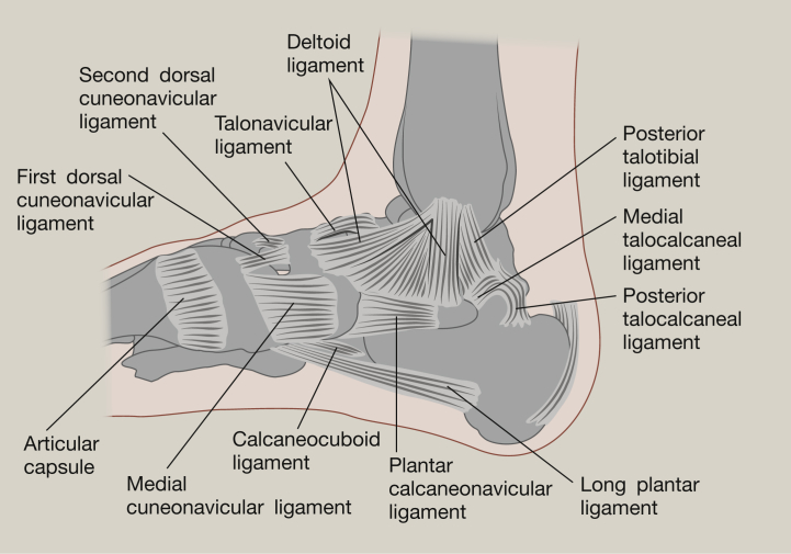
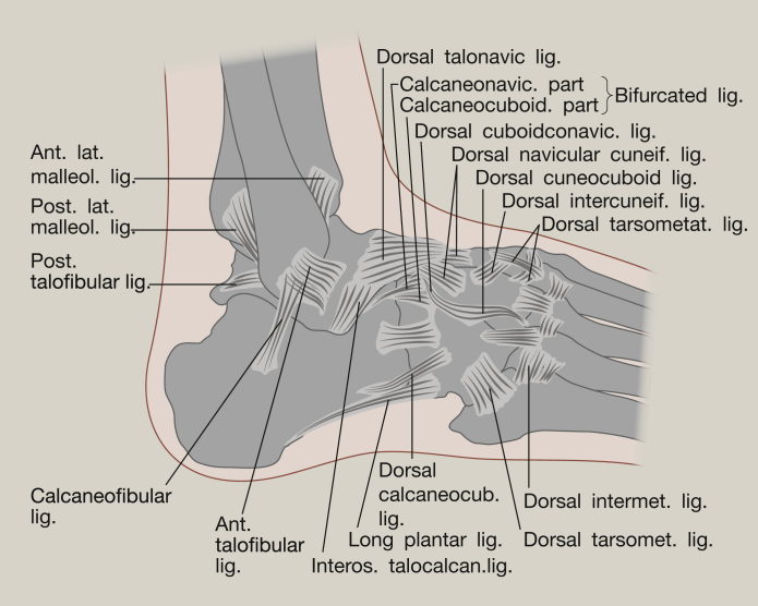
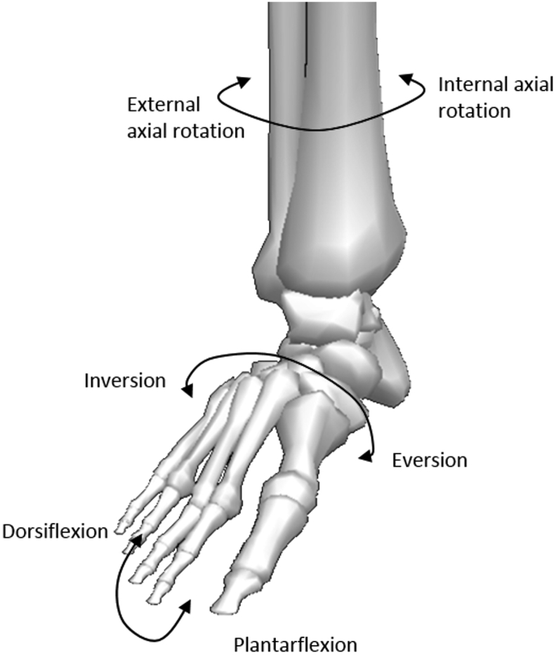
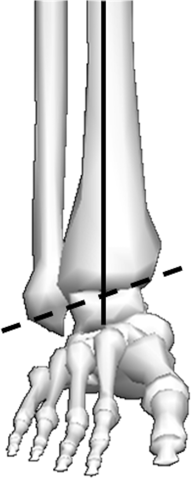
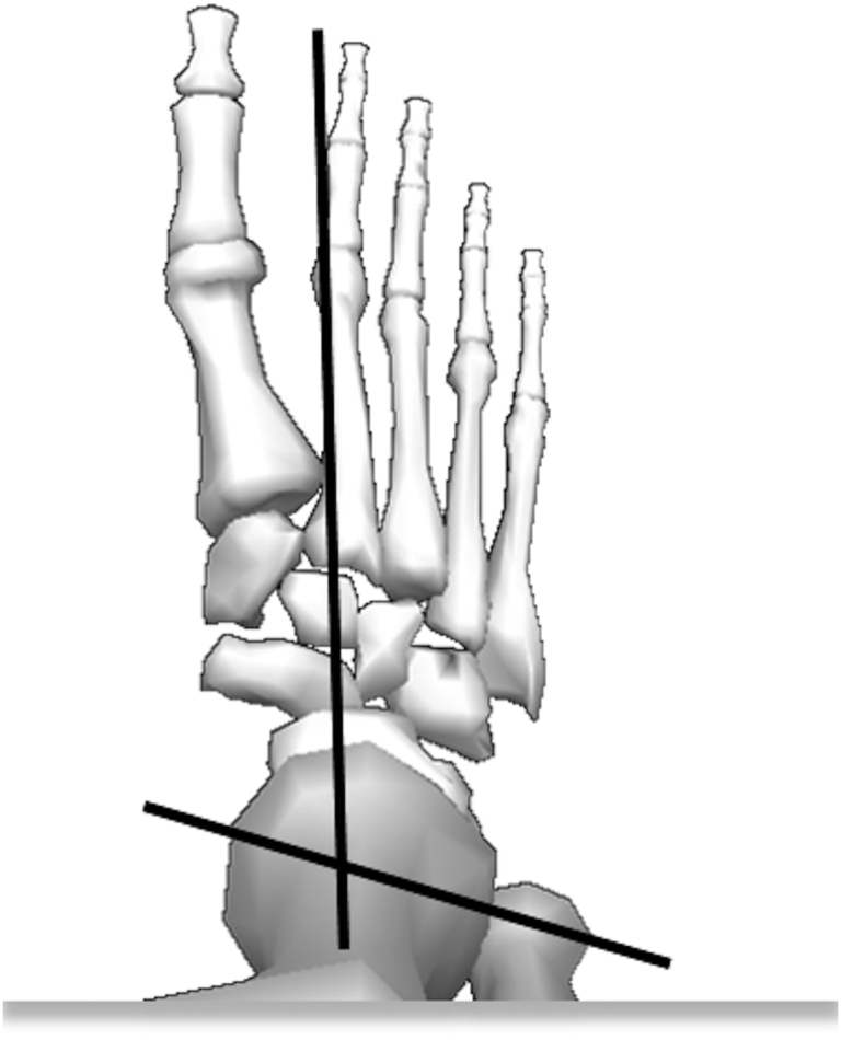
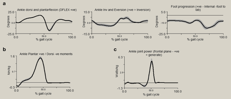
This paper provides an introduction to the biomechanics of the ankle, introducing the bony anatomy involved in motion of the foot and ankle. The complexity of the ankle anatomy has a significant influence on the biomechanical performance of the joint, and this paper discusses the motions of the ankle joint complex, and the joints at which it is proposed they occur. It provides insight into the ligaments that are critical to the stability and function of the ankle joint. It describes the movements involved in a normal gait cycle, and also highlights how these may change as a result of surgical intervention such as total joint replacement or fusion.
Keywords: ankle biomechanics; subtalar joint; talocrural joint; tibiotalar joint.
Figures
References
-
- Gray H. Arcturus Publishing; 2009. Gray's anatomy: with original illustrations by Henry Carter.
-
- Cailliet R. FA Davis Company; 1968. Foot and ankle pain.
-
- Michael J.M., Golshani A., Gargac S., Goswami T. Biomechanics of the ankle joint and clinical outcomes of total ankle replacement. J Mech Behav Biomed Mater. 2008;1:276–294. - PubMed
-
- Sarrafian S.K. Biomechanics of the subtalar joint complex. Clin Orthop Relat Res. 1993;290:17–26. - PubMed
-
- Nordin M., Frankel V.H. Lippincott Williams & Wilkins; 2001. Basic biomechanics of the musculoskeletal system.
LinkOut - more resources
Full Text Sources
Other Literature Sources