

Local Multi-Channel RF Surface Coil versus Body RF Coil Transmission for Cardiac Magnetic Resonance at 3 Tesla: Which Configuration Is Winning the Game?
- PMID: 27598923
- PMCID: PMC5012568
- DOI: 10.1371/journal.pone.0161863
Local Multi-Channel RF Surface Coil versus Body RF Coil Transmission for Cardiac Magnetic Resonance at 3 Tesla: Which Configuration Is Winning the Game?
Abstract
Introduction: The purpose of this study was to demonstrate the feasibility and efficiency of cardiac MR at 3 Tesla using local four-channel RF coil transmission and benchmark it against large volume body RF coil excitation.
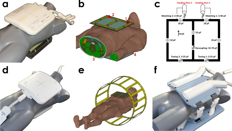
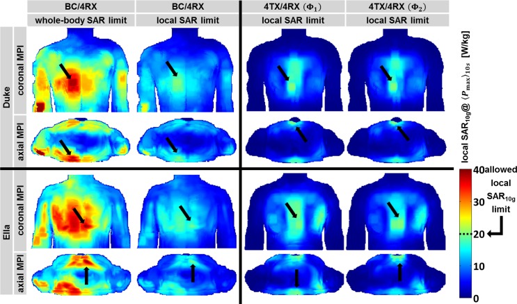
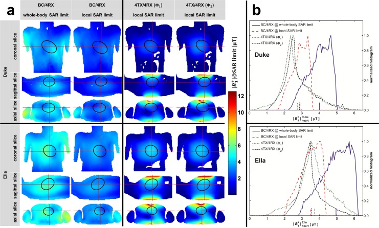
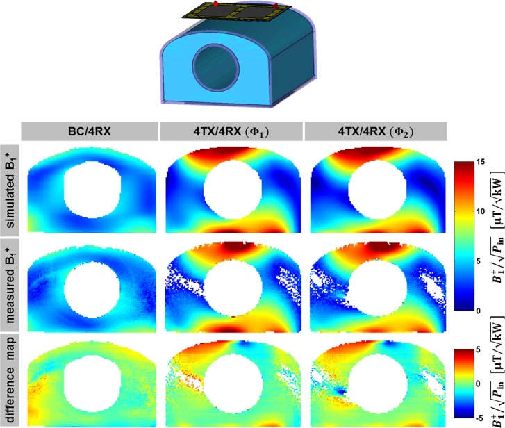
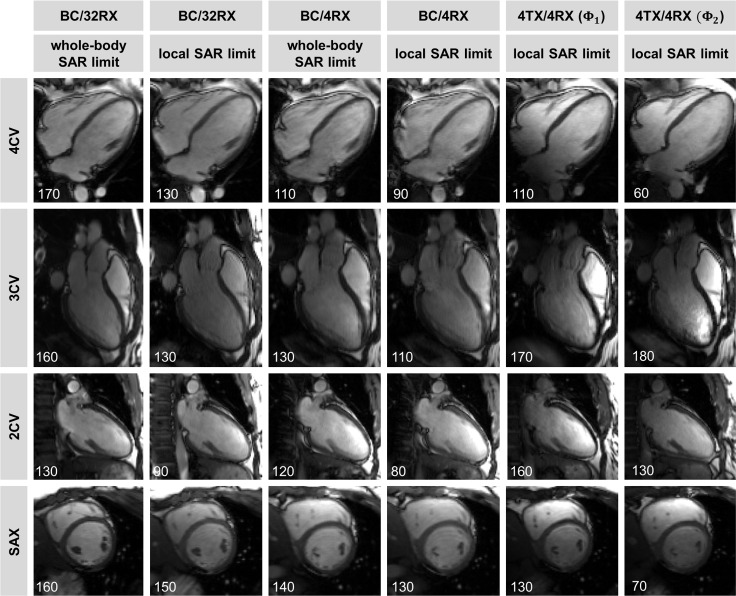
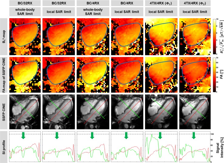
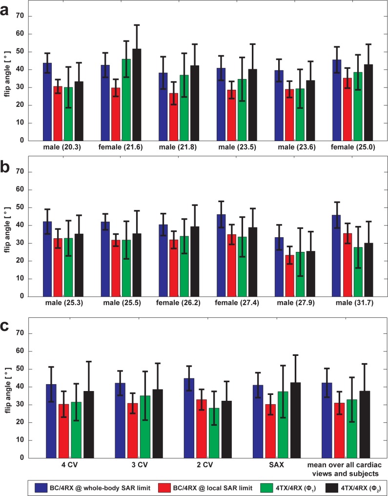
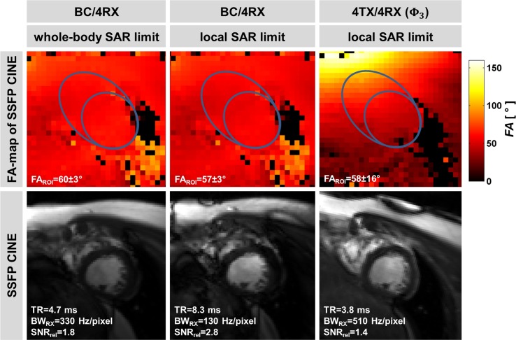
Methods: Electromagnetic field simulations are conducted to detail RF power deposition, transmission field uniformity and efficiency for local and body RF coil transmission. For both excitation regimes transmission field maps are acquired in a human torso phantom. For each transmission regime flip angle distributions and blood-myocardium contrast are examined in a volunteer study of 12 subjects. The feasibility of the local transceiver RF coil array for cardiac chamber quantification at 3 Tesla is demonstrated.
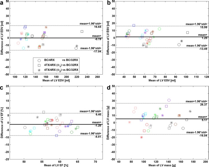
Results: Our simulations and experiments demonstrate that cardiac MR at 3 Tesla using four-channel surface RF coil transmission is competitive versus current clinical CMR practice of large volume body RF coil transmission. The efficiency advantage of the 4TX/4RX setup facilitates shorter repetition times governed by local SAR limits versus body RF coil transmission at whole-body SAR limit. No statistically significant difference was found for cardiac chamber quantification derived with body RF coil versus four-channel surface RF coil transmission. Our simulation also show that the body RF coil exceeds local SAR limits by a factor of ~2 when driven at maximum applicable input power to reach the whole-body SAR limit.
Conclusion: Pursuing local surface RF coil arrays for transmission in cardiac MR is a conceptually appealing alternative to body RF coil transmission, especially for patients with implants.
Conflict of interest statement
Andre Kuehne and Jan Rieger are employees of MRI.TOOLS GmbH, Berlin, Germany. Thoralf Niendorf is founder and CEO of MRI.TOOLS GmbH, Berlin. Germany. The authors confirm that this commercial affiliation does not alter their adherence to PLOS ONE policies on sharing data and materials. Matthias Dieringer is currently employed by Siemens Healthcare, Berlin, Germany His contributions to this work, however, happened when he was employed at Charite', University Medicine, Berlin, Germany. Therefore, Siemens did not provide funding or play a role in the study design, data collection and analysis, decision to publish, or preparation of the manuscript. The authors confirm that this commercial affiliation does not alter their adherence to PLOS ONE policies on sharing data and materials. Antonino Cassara is currently employed by the IT'IS Foundation, Zurich, Switzerland. His contributions to this work, however, happened when he was employed at PTB, Berlin, Germany. Therefore, IT'IS did not provide funding or play a role in the study design, data collection and analysis, decision to publish, or preparation of the manuscript. The authors confirm that this commercial affiliation does not alter their adherence to PLOS ONE policies on sharing data and materials.
Figures
Similar articles
-
RF safety assessment of a bilateral four-channel transmit/receive 7 Tesla breast coil: SAR versus tissue temperature limits.Med Phys. 2017 Jan;44(1):143-157. doi: 10.1002/mp.12034. Med Phys. 2017. PMID: 28102957
-
Design and evaluation of a hybrid radiofrequency applicator for magnetic resonance imaging and RF induced hyperthermia: electromagnetic field simulations up to 14.0 Tesla and proof-of-concept at 7.0 Tesla.PLoS One. 2013 Apr 22;8(4):e61661. doi: 10.1371/journal.pone.0061661. Print 2013. PLoS One. 2013. PMID: 23613896 Free PMC article.
-
An 8-channel transceiver 7-channel receive RF coil setup for high SNR ultrahigh-field MRI of the shoulder at 7T.Med Phys. 2017 Dec;44(12):6195-6208. doi: 10.1002/mp.12612. Epub 2017 Oct 28. Med Phys. 2017. PMID: 28976586
-
Ultra-high field MRI: parallel-transmit arrays and RF pulse design.Phys Med Biol. 2023 Jan 18;68(2). doi: 10.1088/1361-6560/aca4b7. Phys Med Biol. 2023. PMID: 36410046 Review.
-
Parallel magnetic resonance imaging.Neurotherapeutics. 2007 Jul;4(3):499-510. doi: 10.1016/j.nurt.2007.04.011. Neurotherapeutics. 2007. PMID: 17599714 Free PMC article. Review.
Cited by
-
Global optimization of default phases for parallel transmit coils for ultra-high-field cardiac MRI.PLoS One. 2021 Aug 6;16(8):e0255341. doi: 10.1371/journal.pone.0255341. eCollection 2021. PLoS One. 2021. PMID: 34358243 Free PMC article.
-
Extended RF shimming: Sequence-level parallel transmission optimization applied to steady-state free precession MRI of the heart.NMR Biomed. 2017 Jun;30(6):e3701. doi: 10.1002/nbm.3701. Epub 2017 Feb 14. NMR Biomed. 2017. PMID: 28195684 Free PMC article.
References
-
- Spence DK, Wright SM. Comparison of local and global arrays for MRI. CONCEPT MAGN RESON B. 2007;31B(2):86–94. 10.1002/cmr.b.20088 - DOI
-
- IEC. Medical electrical equipment. Part 2–33: Particular requirements for the safety of magnetic resonance equipment for medical diagnosis. International Electrotechnical Commission. 2015;60601-2-33 Ed.3.2.
-
- IEEE. Recommended Practice for Measurements and Computations of Radio Frequency Electromagnetic Fields With Respect to Human Exposure to Such Fields. Institute of Electrical and Electronics Engineers. 2008;Std C95.3.
-
- Snyder CJ, DelaBarre L, Metzger GJ, van de Moortele PF, Akgun C, Ugurbil K, et al. Initial results of cardiac imaging at 7 Tesla. Magnetic resonance in medicine: official journal of the Society of Magnetic Resonance in Medicine / Society of Magnetic Resonance in Medicine. 2009;61(3):517–24. Epub 2008/12/20. 10.1002/mrm.21895 - DOI - PMC - PubMed
-
- Dieringer MA, Renz W, Lindel T, Seifert F, Frauenrath T, von Knobelsdorff-Brenkenhoff F, et al. Design and application of a four-channel transmit/receive surface coil for functional cardiac imaging at 7T. Journal of magnetic resonance imaging: JMRI. 2011;33(3):736–41. Epub 2011/03/26. 10.1002/jmri.22451 . - DOI - PubMed
MeSH terms
LinkOut - more resources
Full Text Sources
Other Literature Sources
Medical
Miscellaneous
