. 2016 Sep 7;36(36):9365-74.
doi: 10.1523/JNEUROSCI.1099-16.2016.

A Corticocortical Circuit Directly Links Retrosplenial Cortex to M2 in the Mouse

Affiliations

A Corticocortical Circuit Directly Links Retrosplenial Cortex to M2 in the Mouse

Naoki Yamawaki et al. J Neurosci. .

Abstract

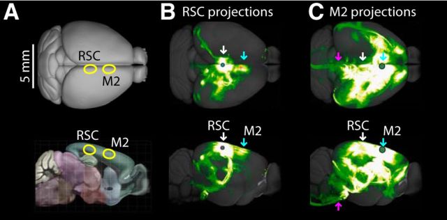
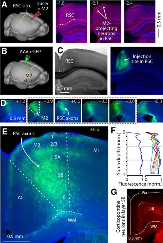
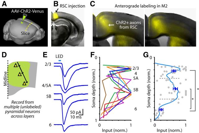
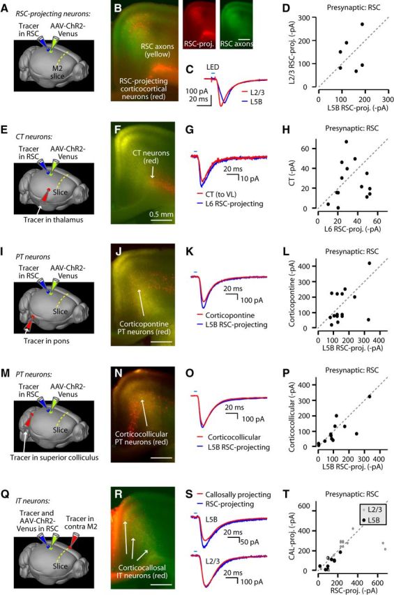
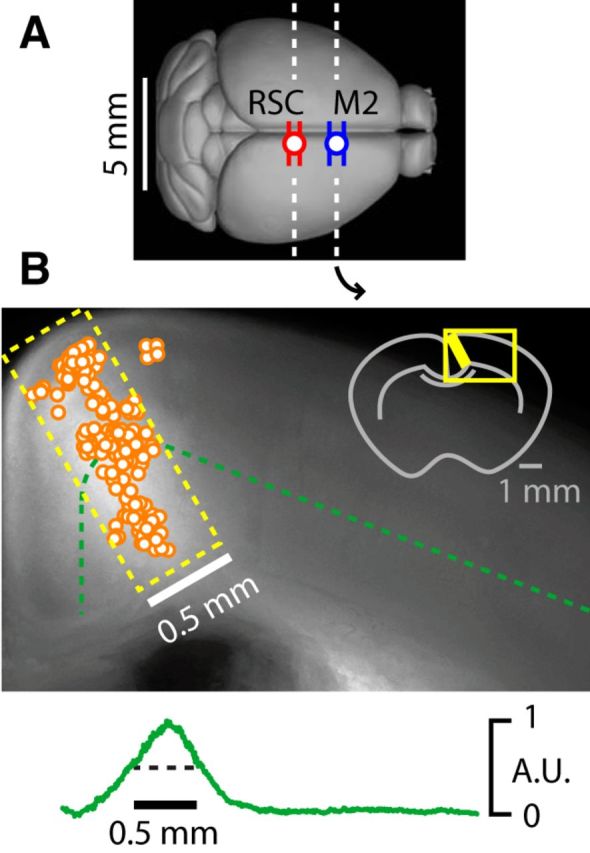
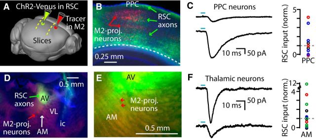
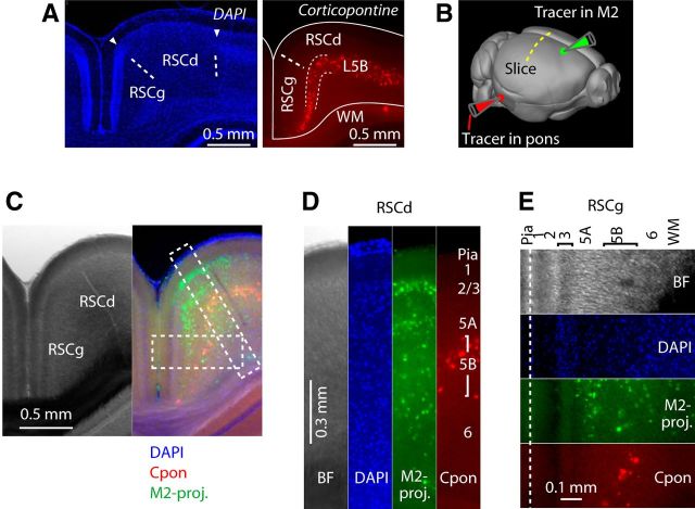
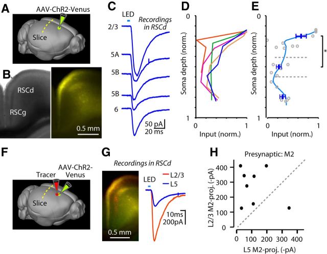
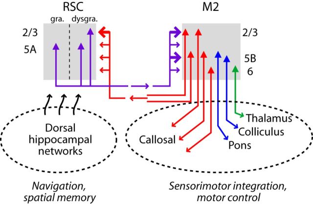
Retrosplenial cortex (RSC) is a dorsomedial parietal area involved in a range of cognitive functions, including episodic memory, navigation, and spatial memory. Anatomically, the RSC receives inputs from dorsal hippocampal networks and in turn projects to medial neocortical areas. A particularly prominent projection extends rostrally to the posterior secondary motor cortex (M2), suggesting a functional corticocortical link from the RSC to M2 and thus a bridge between hippocampal and neocortical networks involved in mnemonic and sensorimotor aspects of navigation. We investigated the cellular connectivity in this RSC→M2 projection in the mouse using optogenetic photostimulation, retrograde labeling, and electrophysiology. Axons from RSC formed monosynaptic excitatory connections onto M2 pyramidal neurons across layers and projection classes, including corticocortical/intratelencephalic neurons (reciprocally and callosally projecting) in layers 2-6, pyramidal tract neurons (corticocollicular, corticopontine) in layer 5B, and, to a lesser extent, corticothalamic neurons in layer 6. In addition to these direct connections, disynaptic connections were made via posterior parietal cortex (RSC→PPC→M2) and anteromedial thalamus (RSC→AM→M2). In the reverse direction, axons from M2 monosynaptically excited M2-projecting corticocortical neurons in the RSC, especially in the superficial layers of the dysgranular region. These findings establish an excitatory RSC→M2 corticocortical circuit that engages diverse types of excitatory projection neurons in the downstream area, suggesting a basis for direct communication from dorsal hippocampal networks involved in spatial memory and navigation to neocortical networks involved in diverse aspects of sensorimotor integration and motor control.

Significance statement: Corticocortical pathways interconnect cortical areas extensively, but the cellular connectivity in these pathways remains largely uncharacterized. Here, we show that a posterior part of secondary motor cortex receives corticocortical axons from the rostral retrosplenial cortex (RSC) and these form monosynaptic excitatory connections onto a wide spectrum of excitatory projection neurons in this area. Our results define a cellular basis for direct communication from RSC to this medial frontal area, suggesting a direct link from dorsal hippocampal networks involved in spatial cognition and navigation (the "map") to sensorimotor networks involved the control of movement (the "motor").

Keywords: circuit; motor; neocortex; optogenetic; retrosplenial.


Figures

Figure 1.
Figure 1.
Allen Mouse Brain Connectivity Atlas images suggest an anatomical basis for RSC corticocortical connections to posterior M2. A, Dorsal (top row) and sagittal (bottom row) views of the mouse brain indicating the locations of the RSC and M2 areas examined in this study. B, Injection in the RSC (white arrow) shows a corticocortical projection to M2 in the posteromedial frontal cortex (cyan arrow). C, Injection in the M2 (cyan arrow), corresponding to the RSC-recipient zone, shows projections to diverse regions including back to the RSC (white arrow) and subcortical regions such as the pyramidal tract (magenta arrow). Images are maximum intensity projections that were viewed, copied, and modified from experiments 100148142 (RSC injection) and 180916954 (M2 injection) of the Allen Mouse Brain Connectivity Atlas.
Figure 2.
Figure 2.
RSC axons project to posterior M2. A, Left, Retrograde tracer injection into the M2 to identify M2-projecting neurons in RSC brain slices. Right, Rostrocaudal series of epifluorescence images showing labeling of M2-projecting neurons (red) in the RSC. Distance from bregma is indicated at the top right. Blue, DAPI staining. Arrows, M2-projecting neurons located in the upper layers of the RSC. B, Schematic showing injection of AAV-eGFP into the RSC for anterograde labeling of RSC axons in M2. C, Bright-field (left) and epifluorescence (right) images of an RSC injection site (green). Blue, DAPI staining. D, Rostrocaudal series of epifluorescence images showing labeling of RSC axons in the M2. Labeling is densest at the cortical flexure, where lateral agranular cortex curves medially into the interhemispheric fissure. Numbers in each image indicate the distance from bregma. Red rectangle indicates range of slices used for recording. Blue, DAPI staining. E, Enlargement of the third image in E with cortical layers indicated. WM, White matter. M1 is laterally adjacent to the M2 and the anterior cingulate (AC) is medially adjacent. F, Normalized fluorescent intensity across layers, for the slice in E (left) and for a total of nine slices (right). Dashed lines indicate layer 5B. G, Layer 5B in M2 (between dashed lines) defined by retrogradely labeled corticopontine neurons. Layer 5B is a relatively thick layer in M2, spanning approximately the middle third of the cortex.
Figure 3.
Figure 3.
RSC axons monosynaptically excite pyramidal neurons across multiple layers in M2. A, Schematic of the experimental paradigm, indicating injection of anterograde tracer (AAV-ChR2-Venus) into the RSC, resulting in anterograde labeling of RSC axons projecting to M2. B, Low-magnification bright-field image merged with epifluorescence image showing the location of the RSC injection site. C, Merged bright-field and epifluorescence images of brain slices containing the M2 and RSC axons over a range of rostrocaudal levels, similar to Figure 2, D and E. D, Schematic of experimental paradigm: M2-projecting axons of RSC neurons were anterogradely labeled and M2 slices were subsequently prepared. In each slice, multiple M2 pyramidal neurons were recorded at different cortical depths along the same radial axis (arrows). E, Example traces recorded from multiple neurons in the same slice. F, Collection of laminar profiles from a different slice (indicated with different color). The blue profile is from the traces in E. G, Data from F are replotted (gray circles) and grouped by dividing the cortical depths into thirds (indicated by dashed lines), which corresponds approximately to layer 2 through 5A in the top third, layer 5B in the middle third, and layer 6 in the bottom third. Blue symbols represent the mean ± SEM for each group. Rank-sum tests for the three groups (significance defined as p < 0.05/3 = 0.0167 to correct for multiple comparisons) showed the following: top versus middle, p = 0.44; middle versus bottom, p = 1.8e-04; and top versus bottom, p = 9.7e-05. The data were fit with a polynomial function (light blue trace; generated with Matlab's cftool using the smoothing spline option with the smoothing parameter set to 0.999973).
Figure 4.
Figure 4.
RSC axons excite diverse projection neurons in M2. A, Schematic of the experimental paradigm: to assess RSC input to RSC-projecting neurons in M2, retrograde tracer (CTB647) and AAV-ChR2-Venus were injected into the RSC. B, Left, Merged epifluorescence image of M2 slice containing RSC-projecting neurons (red) and RSC axons (yellow) in M2. Unmerged epifluorescence images are shown on the right. C, Example traces of photo-evoked RSC input recorded from layer 2/3 (red) and layer 5B (blue) RSC-projecting neurons in M2. D, Group comparison of RSC input to layer 2/3 and layer 5B RSC-projecting neurons (not significantly different; see Results). E, Schematic of the experimental paradigm: to compare RSC input to CT neurons versus RSC-projecting neurons in layer 6, the same injection scheme as in A was used, but with additional injection of retrograde tracer (Retrobeads) into thalamus (ventrolateral nucleus, VL). F, Merged epifluorescence image of brain slices containing CT neurons (red) and RSC axons (yellow) in M2. G, Example traces of RSC input recorded from neighboring CT neurons (red) and RSC-projecting neurons (blue) in M2 layer 6. H, Group comparison of RSC input to CT and RSC-projecting neurons in layer 6 (not significantly different; see Results). I, Schematic of the experimental paradigm: to compare RSC input to corticopontine-type PT neurons versus RSC-projecting neurons in layer 5B, the same injection scheme as in A was used, but with additional injection of retrograde tracer (Retrobeads) into the pons. J, Merged epifluorescence image of brain slices containing corticopontine PT neurons (red) and RSC axons (yellow) in M2. K, Example traces of RSC input recorded from neighboring corticopontine PT neurons (red) paired with layer 5B RSC-projecting neurons (blue) in M2. L, Group comparison of RSC input to corticopontine PT and layer 5B RSC-projecting neurons (not significantly different; see Results). M, Schematic of the experimental paradigm: to compare RSC input to corticocollicular-type PT neurons versus RSC-projecting neurons in layer 5B, the same injection scheme as in A was used, but with additional injection of retrograde tracer (Retrobeads) into superior colliculus (SC). N, Merged epifluorescence image of brain slices containing corticocollicular PT neurons (red) and RSC axons (yellow) in M2. O, Example traces of RSC input recorded from neighboring corticocollicular PT neurons (red) paired with layer 5B RSC-projecting neurons (blue) in M2. P, Group comparison of RSC input to PT (corticocollicular) and layer 5B RSC-projecting neurons (not significantly different; see Results). Q, Schematic of the experimental paradigm: to compare RSC input to corticocallosal IT neurons and RSC-projecting corticocortical neurons, same injection scheme as in A was used, but with additional injection of retrograde tracer (Retrobeads) into contralateral M2. R, Merged epifluorescence image of brain slices containing corticocallosal IT neurons (red) and RSC axons (yellow) in M2. S, Example traces of RSC input recorded from neighboring corticocallosal IT neurons (red) and RSC-projecting neurons (blue) in M2. T, Group comparison of RSC input to corticocallosal IT neurons and RSC-projecting corticocortical neurons (not significantly different; see Results).
Figure 5.
Figure 5.
Anatomical locations of the RSC injections and M2 recordings. A, Locations along the rostrocaudal axis of the RSC injections (red circle; mean ± SEM) and M2 slices (blue circle; mean ± SEM) used in the experiments. B, Locations in the M2 slices of the recorded neurons (circles) are plotted on a median epifluorescence image of RSC axonal labeling in the M2. Bottom, Fluorescence intensity (plotted in arbitrary units, a.u.) along layer 5B (green dashed line in image).
Figure 6.
Figure 6.
Disynaptic RSC connections to M2 via corticocortical and trans-thalamic circuits. A, Injection strategy. AAV-ChR2-Venus was injected in the RSC to anterogradely label RSC efferent axons and retrograde tracer was injected in the M2 to label M2-projecting neurons. Coronal slices were then prepared and inspected to identify cortical and thalamic regions where RSC axons overlapped with M2-projecting neurons. B, Epifluorescence image of a coronal slice containing the PPC showing anterogradely labeled RSC axons (green) and retrogradely labeled M2-projecting somata (red). Blue, DAPI staining. C, Left, Example traces of RSC input recorded from M2-projecting neurons in layer 2/3 neurons of PPC in one animal. Right, Amplitudes of RSC inputs recorded from nine neurons normalized to the median value per animal (each color represents the set of neurons from one animal). D, Epifluorescence image of the anterior thalamus showing anterogradely labeled RSC axons (green) in the anteroventral nucleus (AV) and retrogradely labeled M2-projecting somata in the AM nucleus (red). Blue, DAPI staining. E, Higher-magnification epifluorescence image showing retrogradely labeled M2-projecting somata (red) in the AM, which partially overlap with anterogradely labeled RSC axons (green) projecting to contralateral thalamus. F, Left, Example traces of RSC input recorded from M2-projecting neurons in AM in one animal recorded in relatively dorsal and mid locations in AM, as indicated. Right, Amplitudes of RSC inputs recorded from 15 neurons normalized to the median value per animal (each color represents the set of neurons from one animal).
Figure 7.
Figure 7.
Areal and laminar distribution of M2-projecting neurons in RSC. A, Left, DAPI stain showing differences in density of upper-layer neurons distinguishing the RSCg and RSCd areas of the RSC. Right, Retrograde labeling from the pons labels corticopontine neurons, the laminar distribution of which can be used to define layer 5B (L5B) in both the RSCd and RSCg. B, Schematic of the experimental paradigm indicating injection of retrograde tracer (red Retrobeads) into the pons and retrograde tracer of another color (green Retrobeads) into the M2 to label corticopontine neurons and M2-projecting neurons in RSC, respectively. C, Bright-field image (left) and merged epifluorescence image (right) of brain slice containing corticopontine (Cpon) and M2-projecting neurons in RSC. Blue, DAPI. D, Labeling in RSCd, as indicated in C. E, Labeling in RSCg, as indicated in C.
Figure 8.
Figure 8.
M2 axons excite M2-projecting neurons in RSC A, Schematic of the experimental paradigm: AAV-ChR2-Venus was injected into the M2 to label M2 axons in RSC slices. B, Bright-field image (left) and epifluorescence image (right) of brain slice containing M2 axons in RSC. C, Example traces recorded from multiple neurons in the same RSC slice. D, Laminar profiles from different slices. Blue trace is the profile for the responses in C. E, Same data as in D, but grouped and averaged (top group, layer 2 through 5A; middle, layer 5B; bottom, layer 6). Rank-sum tests for the three groups (significance defined as p < 0.05/3 = 0.0167 to correct for multiple comparisons) showed the following: top versus middle: p = 0.02; middle versus bottom: p = 0.06; top versus bottom: p = 0.48. Blue lines indicate mean ± SEM for the data points in each group. Gray circles are same data as in D, but unconnected by lines. F, Schematic of the experimental paradigm indicating injection of retrograde tracer (retrobeads) and anterograde tracer (AAV-ChR2-Venus) into the M2 to label M2-projecting neurons and M2 axons in RSC. G, Left, Merged epifluorescence image of M2-projecting neurons (red) and M2 axons (yellow). Right, Example traces of M2 input recorded from L2/3 or L5 M2-projecting neurons in RSC. H, Group comparison of RSC input to L2/3 and L5B RSC-projecting neurons.
Figure 9.
Figure 9.
Schematic of RSC–M2 circuit. In the M2, the PT neurons are blue, IT red, and CT green. In the RSC, the M2-projecting neurons are purple.

Similar articles

Cited by

References

    1. Aggleton JP. Looking beyond the hippocampus: old and new neurological targets for understanding memory disorders. Proc Biol Sci. 2014;281:20140565. doi: 10.1098/rspb.2014.0565. pii. - DOI - PMC - PubMed
    1. Aggleton JP, Nelson AJ. Why do lesions in the rodent anterior thalamic nuclei cause such severe spatial deficits? Neurosci Biobehav Rev. 2015;54:131–144. doi: 10.1016/j.neubiorev.2014.08.013. - DOI - PMC - PubMed
    1. Anderson CT, Sheets PL, Kiritani T, Shepherd GMG. Sublayer-specific microcircuits of corticospinal and corticostriatal neurons in motor cortex. Nat Neurosci. 2010;13:739–744. doi: 10.1038/nn.2538. - DOI - PMC - PubMed
    1. Brecht M, Krauss A, Muhammad S, Sinai-Esfahani L, Bellanca S, Margrie TW. Organization of rat vibrissa motor cortex and adjacent areas according to cytoarchitectonics, microstimulation, and intracellular stimulation of identified cells. J Comp Neurol. 2004;479:360–373. doi: 10.1002/cne.20306. - DOI - PubMed
    1. Cho J, Sharp PE. Head direction, place, and movement correlates for cells in the rat retrosplenial cortex. Behav Neurosci. 2001;115:3–25. doi: 10.1037/0735-7044.115.1.3. - DOI - PubMed

Publication types

MeSH terms

LinkOut - more resources