Intraoperative image updating for brain shift following dural opening
- PMID: 27611206
- PMCID: PMC5549265
- DOI: 10.3171/2016.6.JNS152953
Intraoperative image updating for brain shift following dural opening
Abstract
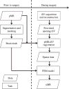
OBJECTIVE Preoperative magnetic resonance images (pMR) are typically coregistered to provide intraoperative navigation, the accuracy of which can be significantly compromised by brain deformation. In this study, the authors generated updated MR images (uMR) in the operating room (OR) to compensate for brain shift due to dural opening, and evaluated the accuracy and computational efficiency of the process. METHODS In 20 open cranial neurosurgical cases, a pair of intraoperative stereovision (iSV) images was acquired after dural opening to reconstruct a 3D profile of the exposed cortical surface. The iSV surface was registered with pMR to detect cortical displacements that were assimilated by a biomechanical model to estimate whole-brain nonrigid deformation and produce uMR in the OR. The uMR views were displayed on a commercial navigation system and compared side by side with the corresponding coregistered pMR. A tracked stylus was used to acquire coordinate locations of features on the cortical surface that served as independent positions for calculating target registration errors (TREs) for the coregistered uMR and pMR image volumes. RESULTS The uMR views were visually more accurate and well aligned with the iSV surface in terms of both geometry and texture compared with pMR where misalignment was evident. The average misfit between model estimates and measured displacements was 1.80 ± 0.35 mm, compared with the average initial misfit of 7.10 ± 2.78 mm between iSV and pMR, and the average TRE was 1.60 ± 0.43 mm across the 20 patients in the uMR image volume, compared with 7.31 ± 2.82 mm on average in the pMR cases. The iSV also proved to be accurate with an average error of 1.20 ± 0.37 mm. The overall computational time required to generate the uMR views was 7-8 minutes. CONCLUSIONS This study compensated for brain deformation caused by intraoperative dural opening using computational model-based assimilation of iSV cortical surface displacements. The uMR proved to be more accurate in terms of model-data misfit and TRE in the 20 patient cases evaluated relative to pMR. The computational time was acceptable (7-8 minutes) and the process caused minimal interruption of surgical workflow.
Keywords: FEM model; FRE = fiducial registration error; GPU = graphics processing unit; OR = operating room; RMS = root mean square; TRE = target registration error; brain deformation; diagnostic and operative techniques; iMR = intraoperative magnetic resonance imaging scanner; iSV = intraoperative stereovision; iUS = intraoperative ultrasound; image-guided neurosurgery; intraoperative stereovision; pMR = preoperative magnetic resonance images; sparse data; uMR = updated magnetic resonance images.
Conflict of interest statement
The authors report no conflict of interest concerning the materials or methods used in this study or the findings specified in this paper.
Figures


Similar articles
-
Stereovision to MR image registration for cortical surface displacement mapping to enhance image-guided neurosurgery.Med Phys. 2014 Oct;41(10):102302. doi: 10.1118/1.4894705. Med Phys. 2014. PMID: 25281972 Free PMC article.
-
Image Updating for Brain Shift Compensation During Resection.Oper Neurosurg. 2018 Apr 1;14(4):402-411. doi: 10.1093/ons/opx123. Oper Neurosurg. 2018. PMID: 28658934 Free PMC article.
-
Intraoperative fiducial-less patient registration using volumetric 3D ultrasound: a prospective series of 32 neurosurgical cases.J Neurosurg. 2015 Sep;123(3):721-31. doi: 10.3171/2014.12.JNS141321. Epub 2015 Jul 3. J Neurosurg. 2015. PMID: 26140481 Free PMC article.
-
IBIS: an OR ready open-source platform for image-guided neurosurgery.Int J Comput Assist Radiol Surg. 2017 Mar;12(3):363-378. doi: 10.1007/s11548-016-1478-0. Epub 2016 Aug 31. Int J Comput Assist Radiol Surg. 2017. PMID: 27581336 Review.
-
Multimodal image registration for preoperative planning and image-guided neurosurgical procedures.Neurosurg Clin N Am. 2011 Apr;22(2):197-206, viii. doi: 10.1016/j.nec.2010.12.001. Neurosurg Clin N Am. 2011. PMID: 21435571 Free PMC article. Review.
Cited by
-
Model-based image updating in deep brain stimulation with assimilation of deep brain sparse data.Med Phys. 2023 Dec;50(12):7904-7920. doi: 10.1002/mp.16578. Epub 2023 Jul 7. Med Phys. 2023. PMID: 37418478 Free PMC article.
-
On the use of fluorescein-based contrast agents as analogs to MRI-gadolinium agents for imaging brain tumors.Proc SPIE Int Soc Opt Eng. 2019 Feb;10862:108620V. doi: 10.1117/12.2510905. Epub 2019 Mar 7. Proc SPIE Int Soc Opt Eng. 2019. PMID: 31929673 Free PMC article.
-
Infrared thermography mapping plus neuronavigation target location in an eloquent area cavernoma resection.Surg Neurol Int. 2020 Mar 13;11:44. doi: 10.25259/SNI_435_2019. eCollection 2020. Surg Neurol Int. 2020. PMID: 32257570 Free PMC article.
-
Precise Brain-shift Prediction by New Combination of W-Net Deep Learning for Neurosurgical Navigation.Neurol Med Chir (Tokyo). 2023 Jul 15;63(7):295-303. doi: 10.2176/jns-nmc.2022-0350. Epub 2023 May 11. Neurol Med Chir (Tokyo). 2023. PMID: 37164701 Free PMC article.
-
Advances of MR imaging in glioma: what the neurosurgeon needs to know.Acta Neurochir (Wien). 2025 Jun 21;167(1):174. doi: 10.1007/s00701-025-06593-6. Acta Neurochir (Wien). 2025. PMID: 40542873 Free PMC article. Review.
References
-
- Buckner JC. Factors influencing survival in high-grade gliomas. Semin Oncol. 2003;30(6 Suppl 19):10–14. - PubMed
-
- Carter TJ, Sermesant M, Cash DM, Barratt DC, Tanner C, Hawkes DJ. Application of soft tissue modelling to image-guided surgery. Med Eng Phys. 2005;27:893–909. - PubMed
-
- Ding S, Miga MI, Thompson RC, Dumpuri P, Cao A, Dawant BM. Estimation of intra-operative brain shift using a tracked laser range scanner. Conf Proc IEEE Eng Med Biol Soc. 2007;2007:848–851. - PubMed
MeSH terms
Grants and funding
LinkOut - more resources
Full Text Sources
Other Literature Sources
Medical

