. 2016 Jun;11(3):330-350.
doi: 10.1016/j.nantod.2016.04.007. Epub 2016 Apr 29.

3D Printed Bionic Nanodevices

Affiliations

3D Printed Bionic Nanodevices

Yong Lin Kong et al. Nano Today. 2016 Jun.

Erratum in

Abstract

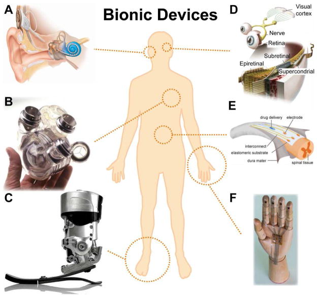
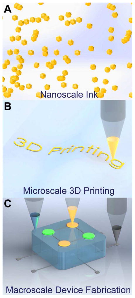
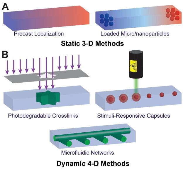
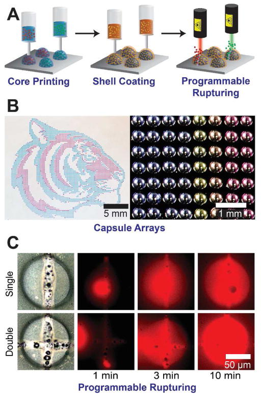
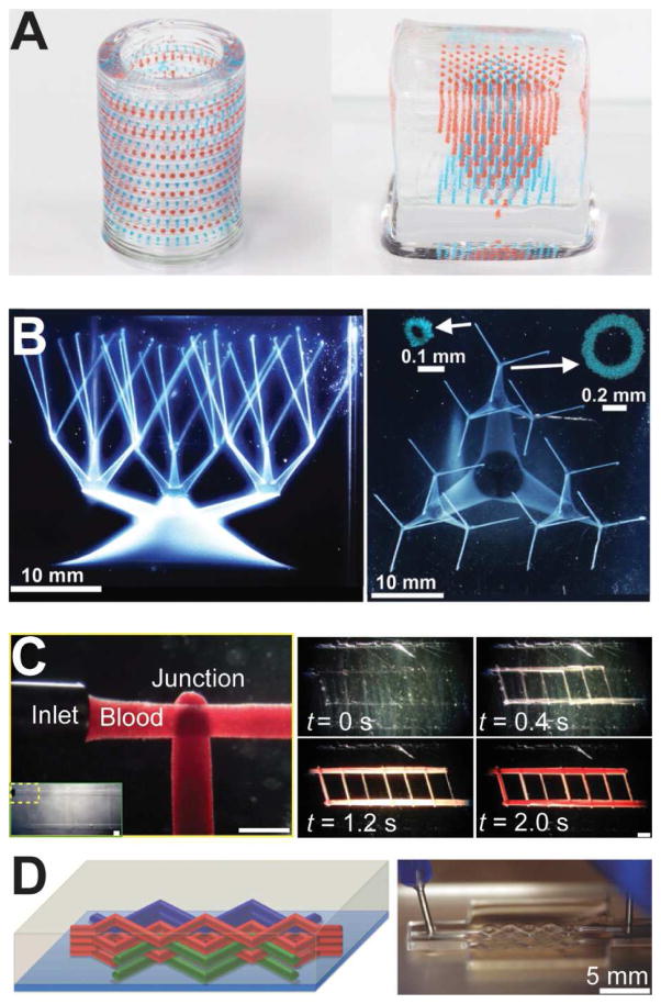
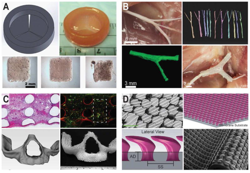
The ability to three-dimensionally interweave biological and functional materials could enable the creation of bionic devices possessing unique and compelling geometries, properties, and functionalities. Indeed, interfacing high performance active devices with biology could impact a variety of fields, including regenerative bioelectronic medicines, smart prosthetics, medical robotics, and human-machine interfaces. Biology, from the molecular scale of DNA and proteins, to the macroscopic scale of tissues and organs, is three-dimensional, often soft and stretchable, and temperature sensitive. This renders most biological platforms incompatible with the fabrication and materials processing methods that have been developed and optimized for functional electronics, which are typically planar, rigid and brittle. A number of strategies have been developed to overcome these dichotomies. One particularly novel approach is the use of extrusion-based multi-material 3D printing, which is an additive manufacturing technology that offers a freeform fabrication strategy. This approach addresses the dichotomies presented above by (1) using 3D printing and imaging for customized, hierarchical, and interwoven device architectures; (2) employing nanotechnology as an enabling route for introducing high performance materials, with the potential for exhibiting properties not found in the bulk; and (3) 3D printing a range of soft and nanoscale materials to enable the integration of a diverse palette of high quality functional nanomaterials with biology. Further, 3D printing is a multi-scale platform, allowing for the incorporation of functional nanoscale inks, the printing of microscale features, and ultimately the creation of macroscale devices. This blending of 3D printing, novel nanomaterial properties, and 'living' platforms may enable next-generation bionic systems. In this review, we highlight this synergistic integration of the unique properties of nanomaterials with the versatility of extrusion-based 3D printing technologies to interweave nanomaterials and fabricate novel bionic devices.

Keywords: 3D printing; 4D printing; active functional devices; bio-nano hybrids; bioelectronics; bionic devices; cyborgs; electronic skins; nanodevices; nanomaterials.


Figures

Figure 1
Figure 1
Bionic technologies for restorative medicine. (A) Cochlear implant [18]. (B) AbioCor self-contained replacement heart [1]. (C) Powered ankle-foot prosthetic controlled by a neuromuscular model [19]. (D) Epiretinal, subretinal, and suprachoroidal implants [21]. (E) Electronic dura mater, “e-dura,” tailored for the spinal cord [22]. (F) A skin-inspired digital mechanoreceptor, where the image shows a model hand with DiTact sensors on the fingertips connected with stretchable interconnects [12]. Reprinted with permission from Refs. [18], [1], [19], [21], [22], [12], respectively. Copyright 2009 Nature Publishing Group, 2002 American Association for the Advancement of Science, 2010 IEEE, 2013 American Association for the Advancement of Science, 2015 American Association for the Advancement of Science.
Figure 2
Figure 2
Multiscale, multi-material 3D printing. (A) Functional nanomaterials can be dispersed in solvents to form solution-processable inks. (B) The inks are then 3D printed at the microscale via extrusion from a suitable nozzle. (C) The three-dimensional co-printing of various classes of materials enables the creation of macroscale functional devices.
Figure 3
Figure 3
Microscale patterning of nanoscale inks on a surface. (A) Challenges inherent to assembling particles via convective self-assembly methods. Top left figure shows formation of so-called “coffee-rings,” typically observed when a colloidal suspension droplet dries on a surface. The photograph is of a deposit left by 100 nm microspheres with a volume fraction of 1%. Top right figure shows non-uniformity in the region of the ring, where the grey scale indicates the density of particles with the white color indicating the highest density. Scale bar is 500 μm [124]. Bottom figure show the superimposed exposures that illustrate the motion of the particles toward the edge of the droplet during the drying process [123]. (B) Non-uniformity can be reduced by introducing a co-solvent. Top figure shows the deposition of quantum dots from pure toluene, while bottom figure shows an improvement in the morphology via the introduction of 20% dichlorobenzene [61]. Scale bar is 1 mm. (C) Evaporation kinetics and particle interactions with the liquid-air interface can be tailored to achieve monolayer assembly of nanoparticles. Micrograph shows the monolayer produced by a solution of dodecanethiol-ligated 6 nm gold nanocrystals. Inset shows the fast Fourier transform (FFT) of the image [136]. (D) Arrays of quantum dots are generated via stick-slip motion of the contact line. The features are controlled by the velocity profile of the translation stage. Bottom right figure shows the fluorescent microscopy image of grid patterns of the quantum dots. Scale bar is 200 μm [142]. Reprinted with permission from Refs. [124], [123], [61], [136], [142], respectively. Copyright 2000 American Physical Society, 1997 Nature Publishing Group, 2014 American Chemical Society, 2006 Nature Publishing Group, 2010 John Wiley & Sons.
Figure 4
Figure 4
3D printing can create macroscale architectures exhibiting interesting mechanical properties. (A) 3D printing of lightweight cellulose composite. The inset illustrates the alignment of high aspect ratio fillers inside the nozzle (left figure). A plot of Young’s modulus vs. density of 3D printed balsa wood and 3D printed tensile bars with fillers show a factor of 10–20× higher longitudinal Young’s moduli compared to most commercially available 3D printed polymers [63]. (B) Hollow-wood pile structure, where the higher magnification SEM image (bottom image) shows a tri-layer Si/SiO2/Si tube wall [147]. (C) Multi-stable architected materials, where the top sequential images demonstrate that the structure retains a deformed shape after removal of a vertical load. Left and right bottom images show the structures before and after compression, respectively [149]. Reprinted with permission from Refs. [63], [147], [149], respectively. Copyright 2014 John Wiley & Sons, 2006 John Wiley & Sons, 2015 John Wiley & Sons.
Figure 5
Figure 5
Schematic of 3D static and 4D dynamic printing methods to create chemical and biomolecular gradients. (A) Static methods allow for a preprogrammed gradient to be developed, typically based on passive diffusion from payload depots. (B) Dynamic methods allow for “on the fly” active reprogramming of gradients, by including the fourth dimension of time.
Figure 6
Figure 6
(A) Schematic showing a 3D printing strategy to creating stimuli-responsive capsules that can be selectively ruptured to release payloads in response to optical stimuli. Incorporation of gold nanorods in the shells allows the capsules to be ruptured by exposure to laser wavelengths determined by the lengths of the incorporated nanorods. (B) Optical images of complex capsule arrays including a printed ‘tiger’ and a pH gradient array with different colors from an indicator dye. (C) Programmed rupture and release of HRP from capsules by selective laser exposure [62] Reprinted with permission from Ref. [62]. Copyright 2015 American Chemical Society.
Figure 7
Figure 7
3D printing strategies to create gradients in macroscale structures. (A) An emulsion printing strategy to create stimuli-responsive multiplexed arrays of capsules within 3D hydrogel matrices (cylinder outer diameter is 8 mm; cube edge length is 10 mm) [62]. (B) Direct printing of vascular networks in granular media. Jamming of the media allows the printed network to be stabilized as it is printed [177]. (C) A carbohydrate glass is printed as a sacrificial scaffold for the vascular network. Once the gel matrix is cast, the scaffold is dissolved leaving behind open channels (scale bars are 1 mm, left; 2 mm, right) [179]. (D) In this example, the authors use a fugitive ink to create microfluidic channels in a hydrogel. After the channels are formed, the ink is removed by decreasing the temperature to fluidize the fugitive ink [178]. Reprinted with permission from Refs. [62], [177], [179], [178], respectively. Copyright 2015 American Chemical Society, 2015 American Association for the Advancement of Science, 2012 Nature Publishing Group, 2014 John Wiley & Sons.
Figure 8
Figure 8
3D printed anatomical design strategies. (A) 3D printed tri-leaflet heart valve [181]. (B) 3D printed anatomical nerve regeneration pathway [64]. (C) 3D printed vascularized bone architectures [182]. (D) 3D printed biomimetic artificial skin (green scale bar is 200 μm) [183]. Reprinted with permission from Refs. [181], [64], [182], [183] respectively. Copyright 2014 Elsevier, 2015 John Wiley & Sons, 2014 John Wiley & Sons.
Figure 9
Figure 9
Mechanical design methodologies in 3D printed biological systems. (A) 3D printed microchannels control the growth of axonal networks in a 3D printed nervous system on a chip [65]. (B)3D printed microgrooves in elastomeric anatomical nerve guides control the alignment of the regenerating axonal network longitudinally toward the injury site. Scale bar is 1 mm [64]. (C) 3D printed spider web displaying interacting radial and spiral elastomeric filaments [186]. Reprinted with permission from Refs. [65], [64], [186], respectively. Copyright 2015 Centre National de la Recherche Scientifique (CNRS) and Royal Society of Chemistry, 2015 John Wiley & Sons, 2015 Nature Publishing Group.
Figure 10
Figure 10
Biochemical design strategies in 3D printed biological systems. (A) Path-specific 3D printed multi-component gradient in anatomical nerve regeneration pathways [64]. (B) Effect of the functional 3D printed path-specific regeneration on the regeneration of motor and sensory nerve pathways, and the functional return of complex regenerated peripheral nerve injuries [64]. Reprinted with permission from Ref. [64]. Copyright 2015 Royal Society of Chemistry.
Figure 11
Figure 11
3D printing of conducting electronic inks. (A) Omni-directional printing of a concentrated silver ink to form the interconnects of an LED chip array. The inset shows an interconnect arch printed over a junction [90]. (B) 3D printing of free-standing liquid metal into a cubic array of stacked droplets (top inset), a 3D metal arch (middle inset), an arch overpassing a printed wire (bottom inset), and a tower of liquid metal droplets. Scale bars are 500 μm [70]. (C) 3D printing of a silver nanoparticle ink on a three dimensional surface to form an antenna [191]. (D) Embedded 3D printing of conducting carbon grease in an uncured elastomeric polymer (inset) enables the creation of stretchable strain sensors embedded within a glove [192]. (E) Co-printing of a conductor within a cell-laden biological scaffold to create a bionic ear. (F) Biocompatibility of the printed electronics within the biological construct. The fluorescent image (bottom) shows the viability of the neo-cartilaginous tissue in contact with the electrode (top) [67]. (G) Electromagnetic response of the 3D printed bionic ear. Plot shows the S21 transmission coefficient with frequency, demonstrating the capability of receiving signals over an expansive frequency range [67]. Reprinted with permission from Refs. [90], [70], [191], [192], [67], respectively. Copyright 2009 American Association for the Advancement of Science, 2011 John Wiley & Sons, 2014 John Wiley & Sons, 2013 American Chemical Society.
Figure 12
Figure 12
3D printing of active electronics with semiconducting inks. (A) 3D Printing of Li3Ti4O12 (LTO) and LiFePO4 (LFP) inks to create a 3D interdigitated micro-battery architecture [196]. (B) SEM images of the printed 3D interdigitated micro-battery. (C) The cycle life of the 3D printed interdigitated battery. A good cycle life is achieved due to the low-strain topotactic reactions of LFP and LTO. (D) A 3D printed quantum dot light-emitting diode (QD-LED), where the inset shows the electroluminescence output from the QD-LED and the graph shows the current density vs. voltage and forward luminance output [61]. (E) Normalized electroluminescence spectra from both green and orange-red QD-LEDS, demonstrating color tunability and high color purity of the 3D printed QD-LEDS. (F) 3D printed QD-LED on a scanned curvilinear substrate, where the figure shows the CAD model and its components. The inset shows the electroluminescence output from the printed QD-LED on a 3D scanned contact lens (lens diameter is 10 mm) [61]. (G) 3D printing of a 2 × 2 × 2 multidimensional array of embedded QD-LEDs, where the inset shows the electroluminescence from a QD-LED in the 3D matrix (cube edge length is 15 mm) [61]. Reprinted with permission from Refs. [196], [61], respectively. Copyright 2013 John Wiley & Sons, 2014 American Chemical Society.

References

    1. Lavine M, Roberts L, Smith O. Science. 2002;295:995. - PubMed
    1. Craelius W. Science. 2002;295:1018–1021. - PubMed
    1. Clausen J. Nature. 2009;457:1080–1081. - PubMed
    1. Vogel G. Science. 2002;295:1020. - PubMed
    1. Dictionary.com. Unabridged. Random House, Inc;