

doi: 10.1039/C6AY01671E.
Epub 2016 Jul 27.
3D-printed Microfluidic Devices: Fabrication, Advantages and Limitations-a Mini Review
Affiliations
- PMID: 27617038
- PMCID: PMC5012532
- DOI: 10.1039/C6AY01671E
Item in Clipboard
3D-printed Microfluidic Devices: Fabrication, Advantages and Limitations-a Mini Review
Anal Methods.
.
Abstract
A mini-review with 79 references. In this review, the most recent trends in 3D-printed microfluidic devices are discussed. In addition, a focus is given to the fabrication aspects of these devices, with the supplemental information containing detailed instructions for designing a variety of structures including: a microfluidic channel, threads to accommodate commercial fluidic fittings, a flow splitter; a well plate, a mold for PDMS channel casting; and how to combine multiple designs into a single device. The advantages and limitations of 3D-printed microfluidic devices are thoroughly discussed, as are some future directions for the field.
Figures
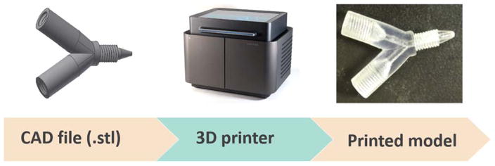
The process to 3D-print a model. The design of a device needs to be realized in a CAD software and converted to .stl format, which can be recognized by a 3D-printer. The printed model is the exact reflection of the CAD design. This example shows the fabrication of a flow splitter using 3D-printing.
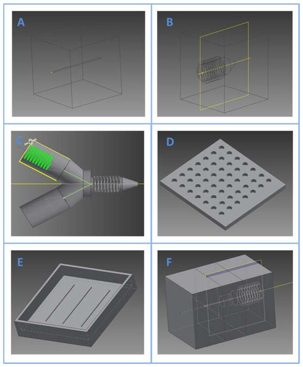
Examples of useful objects for use with microfluidics designed with AutoDesk Inventor. The supporting information shows a step-by-step method for designing each of the objects shown. Listed includes (A), simple straight channel with a circlular cross-section (B), threaded object for integration with a commercial F-230 fitting (Fischer) and F-120 capillary sleeve (Fischer) (C), flow-splitter including both male and female threads for integration with fittings and object containing a channel (D), a simple well plate (E), a mold to create microchannels with soft lithography (F), an example of integrating separate object files into one
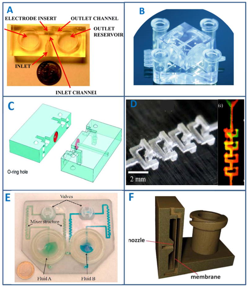
Examples of unique features that can be realized by 3D-printing. (A), a 3D-printed microfluidic device with wall-jet electrochemical configuration. Threaded ports that fit commercial finger tight adapters were 3D-printed on the device. A sample can be introduced through the inlet, which then hits the electrode housed in the “electrode insert” to achieve wall-jet detection. (Adapted from ref. with permission from The Royal Society of Chemistry) (B), luer adapters were 3D-printed on a microfluidic device for easy connection with tubing and syringes. (Adapted from ref. with permission from John Wiley & Sons, Inc) (C), O-rings can be 3D-printed with rubber-like materials on a fluidic device. In this example, the authors used the printed O-ring to connect different chips. (Adapted from ref. with permission from The Royal Society of Chemistry) (D), A 3D-printed gradient generator. With 3D-printing, complicated channels were fabricated in this example. (Adapted from ref. with permission from The American Chemical Society) (E), A 3D-printed microfluidic mixer. By fabricating zigzag channels and vales, two liquids can be mixed well using the device. (Adapted from ref. with permission from Elsevier) (F), A 3D-printed pneumatic valve. The “membrane” is a thin layer (~200 μm) of 3D-printed structure. When proper air pressure is applied through the nozzle, the membrane can deform to open or close the channel on the right side. (Adapted from ref. with permission from The Royal Society of Chemistry)
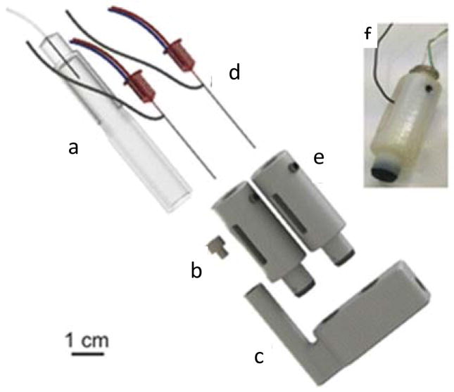
An integrated 3D-printed microfluidic system for metabolite detection. Part (a) is the outlet of a dialysis probe that collects samples from a human being. Via part (b), which is a 3D-printed adapter, (a) can be connected to the 3D-printed microfluidic device (c). Two electrodes (d) were housed in 3D-printed adapters (e), which can be screwed into the microfluidic channel with a good sealing. When a sample is collected and flowing through the channel, glucose and lactate can then be electrochemically detected. (f) is a real picture of a housed electrode and the black part was 3D-printed using a rubber-like material for tight sealing. (Adapted from ref. with permission from The American Chemical Society)
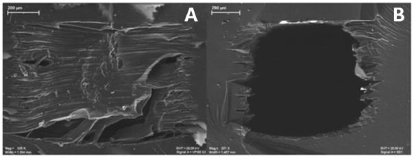
The SEM images of a 3D-printed channel before and after removing supporting material. (A), upon printed, the channel was completely filled with the supporting material, which is commonly used in high resolution 3D-printers. (B), after removal of the supporting material, rough surfaces can be seen on the inner wall of the channel. The scale bars in the images represent 200 μm. (Adapted from ref. with permission from The American Chemical Society)
References
-
- Fujii T. Microelectron Eng. 2002;61–2:907–914.
-
- Terry SC, Jerman JH, AJB IEEE Transactions on Electron Devices. 1979;26:1880–1886.
-
- Harrison DJ, Manz A, Fan ZH, Ludi H, Widmer HM. Anal Chem. 1992;64:1926–1932.
-
- Manz A, Graber N, Widmer HM. Sensor Actuat B-Chem. 1990;1:244–248.
-
- Jacobson SC, Hergenroder R, Koutny LB, Ramsey JM. Anal Chem. 1994;66:1114–1118.
Grants and funding
LinkOut - more resources
Full Text Sources
Other Literature Sources