. 2016 Sep 7;6(3):39.
doi: 10.3390/brainsci6030039.

Investigation into Deep Brain Stimulation Lead Designs: A Patient-Specific Simulation Study

Affiliations

Investigation into Deep Brain Stimulation Lead Designs: A Patient-Specific Simulation Study

Fabiola Alonso et al. Brain Sci. .

Abstract

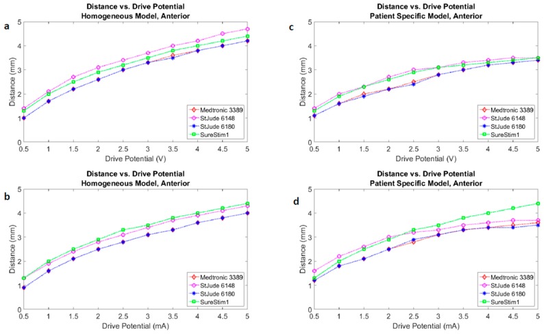
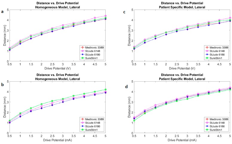
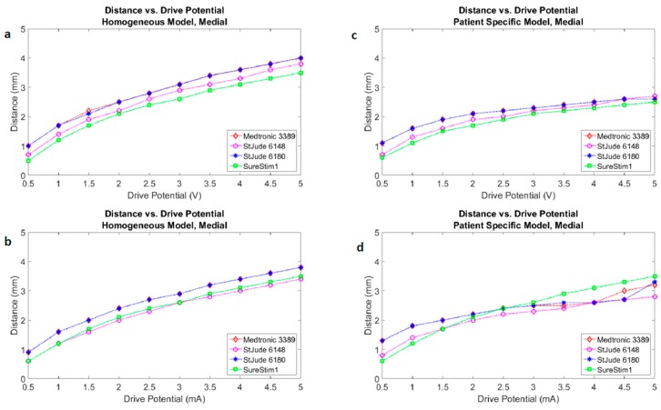
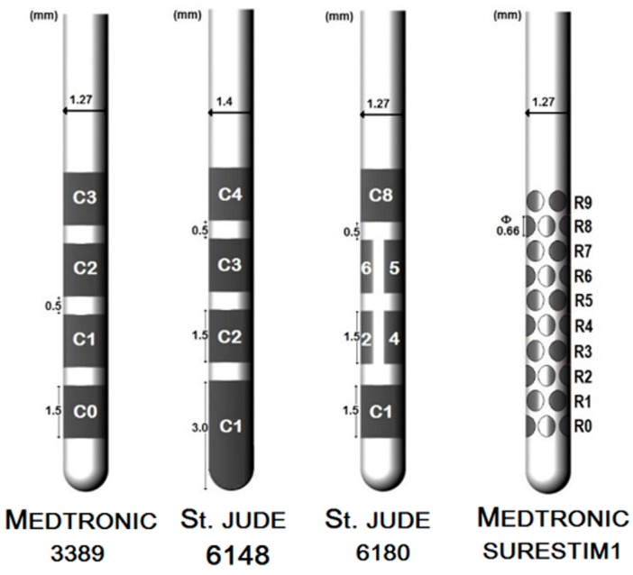
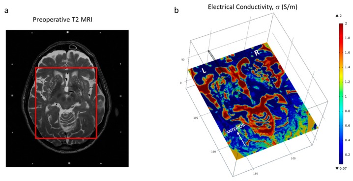
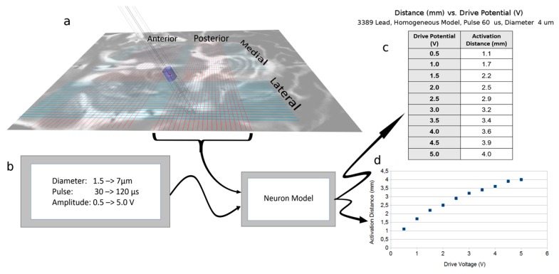
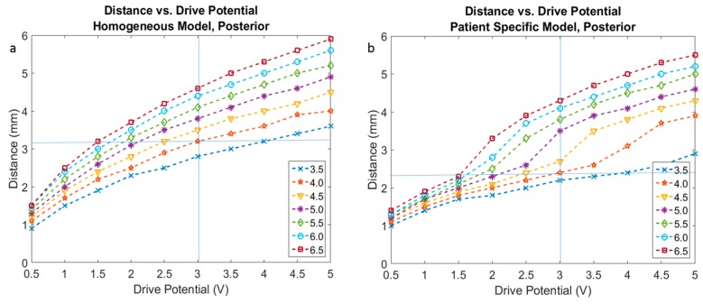
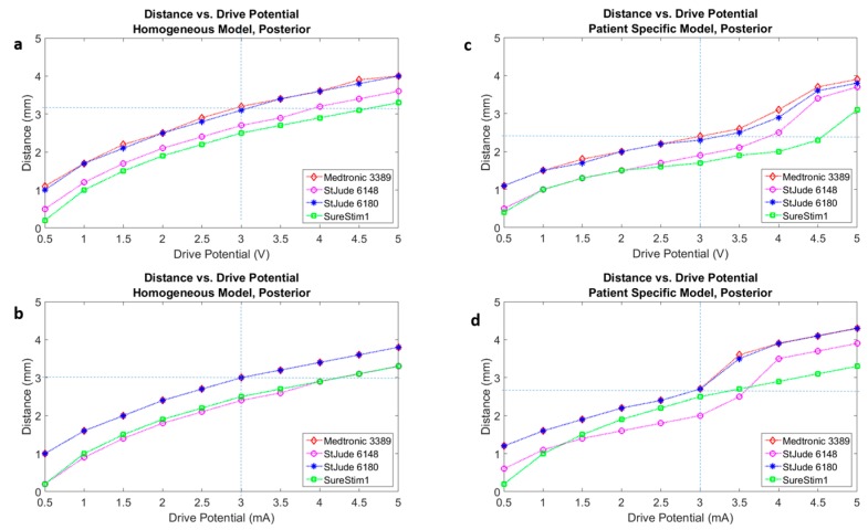
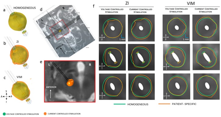
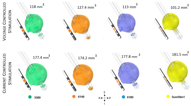
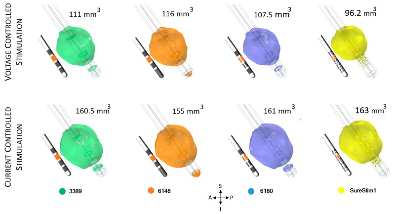
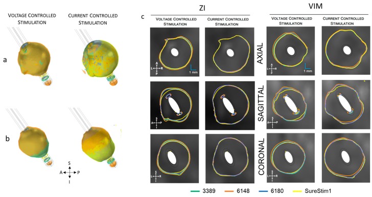
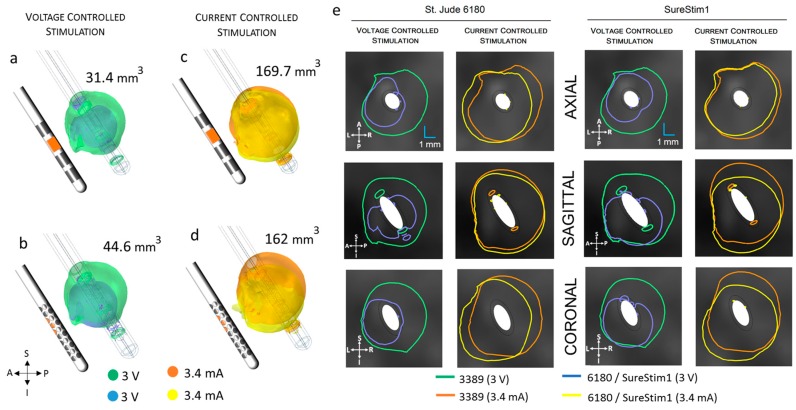
New deep brain stimulation (DBS) electrode designs offer operation in voltage and current mode and capability to steer the electric field (EF). The aim of the study was to compare the EF distributions of four DBS leads at equivalent amplitudes (3 V and 3.4 mA). Finite element method (FEM) simulations (n = 38) around cylindrical contacts (leads 3389, 6148) or equivalent contact configurations (leads 6180, SureStim1) were performed using homogeneous and patient-specific (heterogeneous) brain tissue models. Steering effects of 6180 and SureStim1 were compared with symmetric stimulation fields. To make relative comparisons between simulations, an EF isolevel of 0.2 V/mm was chosen based on neuron model simulations (n = 832) applied before EF visualization and comparisons. The simulations show that the EF distribution is largely influenced by the heterogeneity of the tissue, and the operating mode. Equivalent contact configurations result in similar EF distributions. In steering configurations, larger EF volumes were achieved in current mode using equivalent amplitudes. The methodology was demonstrated in a patient-specific simulation around the zona incerta and a "virtual" ventral intermediate nucleus target. In conclusion, lead design differences are enhanced when using patient-specific tissue models and current stimulation mode.

Keywords: brain model; deep brain stimulation (DBS); electric field; electrode design; finite element method; neuron model; patient-specific; steering; zona incerta (ZI).


Conflict of interest statement

The authors declare no conflict of interest.

Figures

Figure A1
Figure A1
Neuron modelling: Distance vs. drive potential. Anterior.
Figure A2
Figure A2
Neuron modelling: Distance vs. drive potential. Lateral.
Figure A3
Figure A3
Neuron modelling: Distance vs. drive potential. Medial.
Figure 1
Figure 1
Representation of the conventional and the steering field leads.
Figure 2
Figure 2
(a) Demarcation of the region of interest on the patient T2 MRI dataset (cauda-cranial point of view) and (b) Brain model displaying one slice of the interpolated conductivity matrix (cranio-caudal point of view) and the trajectory of the lead. Axial images displayed at the level of the ZI.
Figure 3
Figure 3
Neuron model application and single calculation run. (a) The voltage gradient extraction lines generated from FEM (COMSOL) simulation. The posterior lines have been replaced by the real potential values along the lines, as can be seen by the deviation of the line close to the electrode; (b) Input to the neuron model and the model block [14]; (c) Data points output from the Neuron model for the 3389 lead, with the specific input parameters of FEM output (homogeneous model and 3389 lead), pulse length of 60 µs, and neuronal diameter of 4 µm. The output is the distance from the surface of the lead to the distance where activation no longer happens; (d) The graphical implementation of the one data set.
Figure 4
Figure 4
Activation distance plots based on FEM analysis for voltage driven lead 3389 with fixed parameters of 60 µs pulse width, drive potentials range of 0.5 to 5 V, and neuron diameters ranging from 3.5 µm to 6.5 µm. (a) Homogeneous tissue model and (b) patient-specific tissue model.
Figure 5
Figure 5
Activation distances for four leads mapped onto a single plot under the same test conditions of 60 µs pulse width, neuron diameter of 4 µm, configuration of all leads in 3389 lead single ring equivalent. (a) Homogeneous tissue model with voltage driven electrode; (b) Homogeneous tissue model with current driven electrode; (c) Patient-specific tissue model with voltage driven electrode; (d) Patient-specific tissue model with current driven electrode.
Figure 6
Figure 6
Electric field (EF) distribution (0.2 V/mm) in voltage and current control stimulation mode. (a) Homogeneous model (b) patient-specific model, ZI and (c) VIM; (d) Axial, sagittal and coronal cut planes, crossing at the middle point of the active contact (e) closer view of the axial plane of the preoperative MRI at the ZI and (f) electric field isocontours (0.2 V/mm) of lead 3389 for homogeneous and patient-specific brain models. EF obtained at 3 V (first and third column) and 3.4 mA (second and fourth column). A: anterior, P: posterior, S: superior, I: inferior, L: left, R: right.
Figure 7
Figure 7
Electric field (EF) simulated at ZI for each lead depicted with an isosurface of 0.2 V/mm. Active contacts (shown in orange in each lead schematic) set to 3 V (first row) and 3.4 mA (bottom row). EF volume within the selected isosurface shown to the right of the lead. A: anterior, P: posterior, S: superior, I: inferior, L: left, R: right.
Figure 8
Figure 8
Electric field (EF) simulated at VIM for each lead depicted with an isosurface of 0.2 V/mm. Active contacts (shown in orange in each lead schematic) set to 3 V (first row) and 3.4 mA (bottom row). EF volume within the selected isosurface shown to the right of the lead. A: anterior, P: posterior, S: superior, I: inferior, L: left, R: right.
Figure 9
Figure 9
Electric field (EF) 0.2 V/mm isosurfaces achieved by each lead superimposed for each EF distribution of each lead operated in voltage (3 V) and current (3.4 mA). (a) EF isosurfaces at ZI in voltage (left) and current (right); (b) isosurfaces at VIM for voltage (left) and current (right); (c) Isocontours (0.2 V/mm) at the axial, sagittal and coronal planes. The cut planes for visualization were placed at the coordinates of the middle point of the active contacts. A: anterior, P: posterior, S: superior, I: inferior, L: left, R: right.
Figure 10
Figure 10
(a) Electric field (EF) distribution when the contact is set to 1.6 V and the equivalent current 1.3 mA (superimposed); (b) Isocontours for voltage and current superimposed. The maximal EF extent using an isolevel of 0.2 V/mm measured from the middle point of the active contact was 2.5 mm in all planes for both operating modes. A: anterior, P: posterior, S: superior, I: inferior, L: left, R: right.
Figure 11
Figure 11
Comparison of the electric field (EF) isosurfaces (0.2 V/mm) at the zona incerta between the standard lead 3389 and the steering leads (active contacts shown in orange in the lead schematic). EF superimposed for lead 3389 (green/orange volumes) and (a) lead 6180 contact 5 active; (b) SureStim1 lead using the diamond configuration, operated in voltage mode (smaller volumes in blue); (c) Lead 6180 and (d) SureStim1 setting the contacts to current mode (EF volumes in yellow); (e) EF isocontours (0.2 V/mm) at the axial, sagittal and coronal planes for both leads operated in voltage and current mode. A: anterior, P: posterior, S: superior, I: inferior, L: left, R: right.

References

    1. Hariz M., Blomstedt P., Zrinzo L. Future of brain stimulation: New targets, new indications, new technology. Mov. Disord. 2013;28:1784–1792. doi: 10.1002/mds.25665. - DOI - PubMed
    1. Martens H.C., Toader E., Decre M.M., Anderson D.J., Vetter R., Kipke D.R., Baker K.B., Johnson M.D., Vitek J.L. Spatial steering of deep brain stimulation volumes using a novel lead design. Clin. Neurophysiol. 2011;122:558–566. doi: 10.1016/j.clinph.2010.07.026. - DOI - PubMed
    1. Mahlknecht P., Limousin P., Foltynie T. Deep brain stimulation for movement disorders: Update on recent discoveries and outlook on future developments. J. Neurol. 2015;262:2583–2595. doi: 10.1007/s00415-015-7790-8. - DOI - PubMed
    1. Gross R.E., McDougal M.E. Technological advances in the surgical treatment of movement disorders. Curr. Neurol. Neurosci. Rep. 2013;13:371. doi: 10.1007/s11910-013-0371-2. - DOI - PMC - PubMed
    1. Hemm S., Mennessier G., Vayssiere N., Cif L., El Fertit H., Coubes P. Deep brain stimulation in movement disorders: Stereotactic coregistration of two-dimensional electrical field modeling and magnetic resonance imaging. J. Neurosurg. 2005;103:949–955. doi: 10.3171/jns.2005.103.6.0949. - DOI - PubMed