. 2014 Mar 1;1(1):75-87.
doi: 10.1089/soro.2013.0009.

Autonomous Soft Robotic Fish Capable of Escape Maneuvers Using Fluidic Elastomer Actuators

Affiliations

Autonomous Soft Robotic Fish Capable of Escape Maneuvers Using Fluidic Elastomer Actuators

Andrew D Marchese et al. Soft Robot. .

Abstract

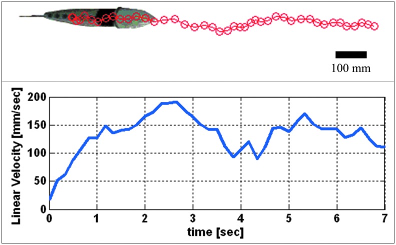
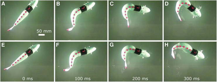
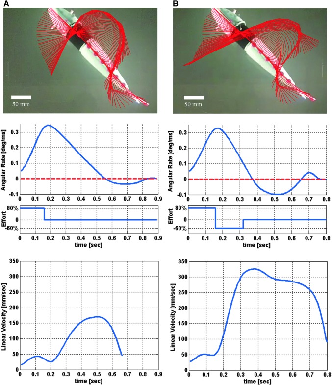
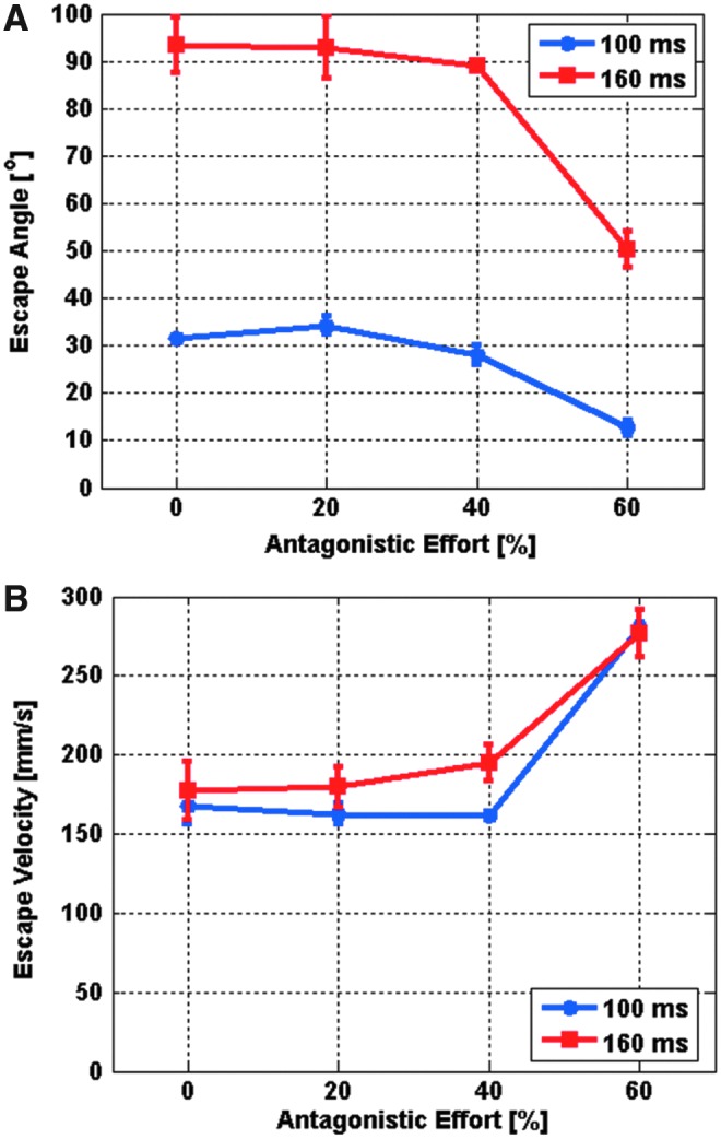
In this work we describe an autonomous soft-bodied robot that is both self-contained and capable of rapid, continuum-body motion. We detail the design, modeling, fabrication, and control of the soft fish, focusing on enabling the robot to perform rapid escape responses. The robot employs a compliant body with embedded actuators emulating the slender anatomical form of a fish. In addition, the robot has a novel fluidic actuation system that drives body motion and has all the subsystems of a traditional robot onboard: power, actuation, processing, and control. At the core of the fish's soft body is an array of fluidic elastomer actuators. We design the fish to emulate escape responses in addition to forward swimming because such maneuvers require rapid body accelerations and continuum-body motion. These maneuvers showcase the performance capabilities of this self-contained robot. The kinematics and controllability of the robot during simulated escape response maneuvers are analyzed and compared with studies on biological fish. We show that during escape responses, the soft-bodied robot has similar input-output relationships to those observed in biological fish. The major implication of this work is that we show soft robots can be both self-contained and capable of rapid body motion.


Figures

<b>FIG. 1.</b>
FIG. 1.
Details of a soft-bodied robotic fish. Top: A dorsal view of the fish showing (A) rigid anterior, (B) center of mass, (C) anterior trunk musclelike actuator pair, (D) inextensible vertebrate-like constraint, (E) posterior trunk actuator pair, and (F) passive caudal fin. Center: A cross-sectional rendering of the mechanism showing (G) fluidic elastomer channels grouped into antagonistic actuator, (H) flexible constraint layer, and (I) pressurized elastomer channels in agonistic actuator. Bottom: An exploded view of the robot detailing (J) silicone skin, (K) communication and control electronics, (L) compressed gas cylinder and regulator, (M) flow control valves, (N) actuator access port, (O) plastic fuselage, (P) videography markers, and (Q) silicone elastomer trunk.
<b>FIG. 2.</b>
FIG. 2.
Schematic representation of a tapered bidirectional FEA in cross section. (A) The three-layer structure: symmetric agonistic (1) and antagonistic (3) expanding layers sandwiching an inextensible but flexible constraining layer (2). Here, embedded channel groupings are in a depressurized state. (B) Pressurized gas (red) expanding the agonistic channel group. Because of the constraining layer, fluid pressure induces a bending moment producing curvature. (C) Model parameters. (D) Predicted curvature of the fish's anterior actuator overlaid atop the actuator's actual deformation. FEA, fluidic elastomer actuator.
<b>FIG. 3.</b>
FIG. 3.
Illustration of the soft fish body fabrication process. First, two halves of the body (1a), a connector piece (1b), and a constraining layer (1c) are all cast from silicone by two-part molds. Next, these four pieces are sequentially bonded together using a thin layer of silicone (2). Lastly, once cured, the fish body is ready for operation (3).
<b>FIG. 4.</b>
FIG. 4.
Pressure–volume profiles of fluid used to fill the anterior agonist actuator at various flow rates. By integrating the change in pressure as a function of displaced volume, the elastic and resistive components of work done on the actuator are determined.
<b>FIG. 5.</b>
FIG. 5.
Details of gas storage, regulation, and release mechanism. The mechanism consists of a high-pressure CO2 gas cylinder (A), a passive mechanical regulator (B), an interface manifold (C), proportional control valves (D), and exhaust valves (E). On the left, red arrows illustrate gas flow during actuator pressurization; on the right, black arrows illustrate gas flow during depressurization.
<b>FIG. 6.</b>
FIG. 6.
Experimental results of the robotic fish during forward swimming. The top panel shows the digitized average body midline position moving as a function of time. The bottom panel details the corresponding linear velocity of the center of mass as a function of time. During this experiment, tail stroke frequency is 1.67 Hz, and a velocity of approximately 150 mm/s is attained.
<b>FIG. 7.</b>
FIG. 7.
Sequences depicting the soft robotic fish performing both a single-bend (A–D) and double-bend (E–H) escape response. The single-bend response requires only agonistic actuator effort. The double-bend response requires sequential agonistic and antagonistic actuator efforts, causing a significant decrease in heading angle and ultimately resulting in lower escape angles than single-bend responses. Actuator effort durations of 160 ms were used in both escape responses.
<b>FIG. 8.</b>
FIG. 8.
Escape response kinematics of the soft-bodied robotic fish. Panel (A) details kinematics of a typical single-bend escape response for the robotic fish; similarly, panel (B) details a double-bend escape response. The top portions of the panels show the digitized body midline (red) overlaid every 10 ms from the first detectable motion to the end of maneuver. The middle portions show the corresponding angular velocity of the head along with actuator effort (agonistic is positive; antagonistic is negative). At the bottom is the resulting center-of-mass velocity for each maneuver.
<b>FIG. 9.</b>
FIG. 9.
Fast-start kinematics of an angelfish. At the top is the body midline plotted for a single-bend (A) and a double-bend (B) fast-start. At the bottom is the corresponding angular velocity profile for the double-bend fast-start. These figures are reproduced with permission from Domenici and Blake and Domenici and Blake, respectively.
<b>FIG. 10.</b>
FIG. 10.
Input–output relationship of escape response maneuvers in the robotic fish. (A) Escape angle as a function of antagonistic actuator effort. (B) Escape velocity as a function of antagonistic actuator effort. In both cases, equal duration agonistic and antagonistic efforts of 100 and 160 ms were used (blue and red lines, respectively). Data points represent mean values (n=4 and n=3 for 100 and 160 ms scenarios, respectively, for a total of 28 tests), and error bars represent standard deviations.

References

    1. Domenici P, Blake RW. The kinematics and performance of fish fast-start swimming. J Exp Biol 1997;200:1165–1178 - PubMed
    1. Borazjani I, Sotiropoulos F, Tytell ED, Lauder GV. Hydrodynamics of the bluegill sunfish C-start escape response: three-dimensional simulations and comparison with experimental data. J Exp Biol 2012;215:671–684 - PubMed
    1. Wakeling JM, Johnston IA. Body bending during fast-starts in fish can be explained in terms of muscle torque and hydrodynamic resistance. J Exp Biol 1999;202:675–682 - PubMed
    1. Jayne BC, Lauder GV. Red and white muscle activity and kinematics of the escape response of the bluegill sunfish during swimming. J Comp Physiol A 1993;173:495–508
    1. Webb PW, Skadsen JM. Strike tactics of Esox. Can J Zool 1980;58:1462–1469 - PubMed