

Stretch Injury of Human Induced Pluripotent Stem Cell Derived Neurons in a 96 Well Format
- PMID: 27671211
- PMCID: PMC5037451
- DOI: 10.1038/srep34097
Stretch Injury of Human Induced Pluripotent Stem Cell Derived Neurons in a 96 Well Format
Abstract
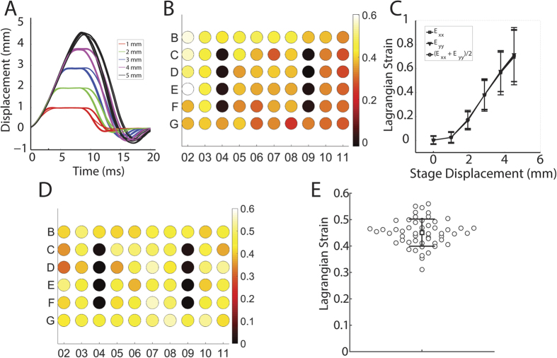
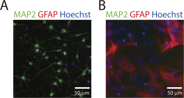
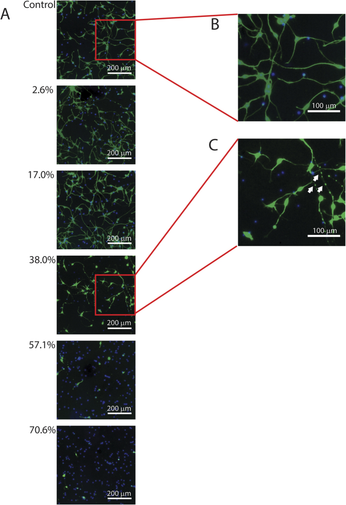
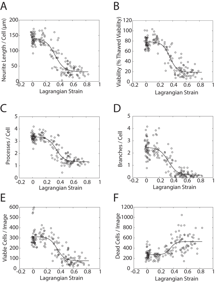
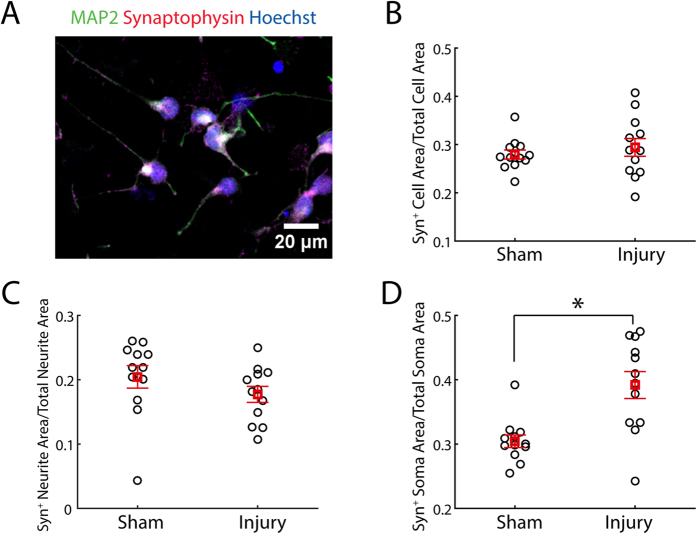
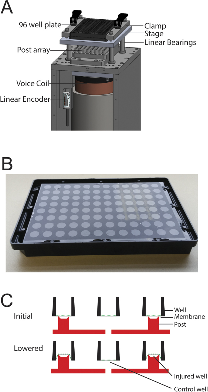
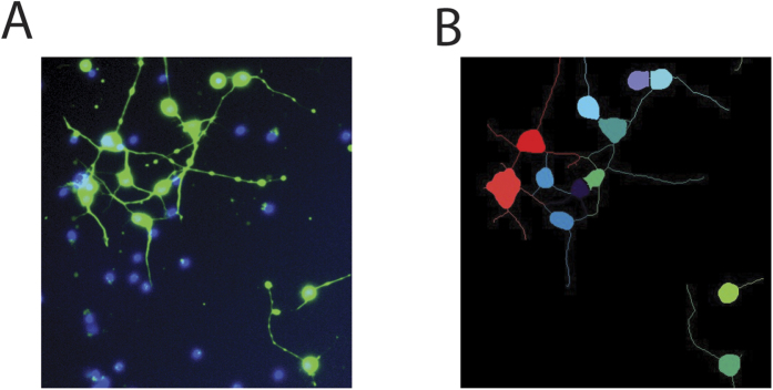
Traumatic brain injury (TBI) is a major cause of mortality and morbidity with limited therapeutic options. Traumatic axonal injury (TAI) is an important component of TBI pathology. It is difficult to reproduce TAI in animal models of closed head injury, but in vitro stretch injury models reproduce clinical TAI pathology. Existing in vitro models employ primary rodent neurons or human cancer cell line cells in low throughput formats. This in vitro neuronal stretch injury model employs human induced pluripotent stem cell-derived neurons (hiPSCNs) in a 96 well format. Silicone membranes were attached to 96 well plate tops to create stretchable, culture substrates. A custom-built device was designed and validated to apply repeatable, biofidelic strains and strain rates to these plates. A high content approach was used to measure injury in a hypothesis-free manner. These measurements are shown to provide a sensitive, dose-dependent, multi-modal description of the response to mechanical insult. hiPSCNs transition from healthy to injured phenotype at approximately 35% Lagrangian strain. Continued development of this model may create novel opportunities for drug discovery and exploration of the role of human genotype in TAI pathology.
Figures
Similar articles
-
Method for High Speed Stretch Injury of Human Induced Pluripotent Stem Cell-derived Neurons in a 96-well Format.J Vis Exp. 2018 Apr 20;(134):57305. doi: 10.3791/57305. J Vis Exp. 2018. PMID: 29733307 Free PMC article.
-
Dorsal root ganglion neurons recapitulate the traumatic axonal injury of CNS neurons in response to a rapid stretch in vitro.Front Cell Neurosci. 2023 Mar 29;17:1111403. doi: 10.3389/fncel.2023.1111403. eCollection 2023. Front Cell Neurosci. 2023. PMID: 37066078 Free PMC article.
-
Traumatic axonal injury in the spinal cord evoked by traumatic brain injury.J Neurotrauma. 2008 Mar;25(3):205-13. doi: 10.1089/neu.2007.0331. J Neurotrauma. 2008. PMID: 18352834
-
Experimental models of traumatic axonal injury.J Clin Neurosci. 2010 Feb;17(2):157-62. doi: 10.1016/j.jocn.2009.07.099. Epub 2009 Dec 29. J Clin Neurosci. 2010. PMID: 20042337 Review.
-
Experimental models of repetitive brain injuries.Prog Brain Res. 2007;161:253-61. doi: 10.1016/S0079-6123(06)61018-2. Prog Brain Res. 2007. PMID: 17618983 Review.
Cited by
-
Current advances in in vitro models of central nervous system trauma.Curr Opin Biomed Eng. 2020 Jun;14:34-41. doi: 10.1016/j.cobme.2020.05.002. Epub 2020 May 14. Curr Opin Biomed Eng. 2020. PMID: 32671312 Free PMC article.
-
Modeling Traumatic Brain Injury in Human Cerebral Organoids.Cells. 2021 Oct 7;10(10):2683. doi: 10.3390/cells10102683. Cells. 2021. PMID: 34685663 Free PMC article.
-
The neurodynamic treatment induces biological changes in sensory and motor neurons in vitro.Sci Rep. 2021 Jun 24;11(1):13277. doi: 10.1038/s41598-021-92682-2. Sci Rep. 2021. PMID: 34168249 Free PMC article.
-
The role of mechanobiology in bone and cartilage model systems in characterizing initiation and progression of osteoarthritis.APL Bioeng. 2022 Jan 5;6(1):011501. doi: 10.1063/5.0068277. eCollection 2022 Mar. APL Bioeng. 2022. PMID: 40746901 Free PMC article. Review.
-
Characterization of Biaxial Stretch as an In Vitro Model of Traumatic Brain Injury to the Blood-Brain Barrier.Mol Neurobiol. 2018 Jan;55(1):258-266. doi: 10.1007/s12035-017-0738-5. Mol Neurobiol. 2018. PMID: 28842857
References
-
- Faul M., Xu L., Wald M. M. & Coronado V. ‘Traumatic Brain Injury in the United States: Emergency Department Visits, Hospitalizations and Deaths 2002–2006’. Date of access: 01/09/2016 (2010).
-
- Holbourn A. H. S. Mechanics of Head Injuries. The Lancet 243, 483 (1943).
LinkOut - more resources
Full Text Sources
Other Literature Sources
