. 2016 Oct 18;113(42):11703-11708.
doi: 10.1073/pnas.1605271113. Epub 2016 Sep 26.

Layerless fabrication with continuous liquid interface production

Affiliations

Layerless fabrication with continuous liquid interface production

Rima Janusziewicz et al. Proc Natl Acad Sci U S A. .

Abstract

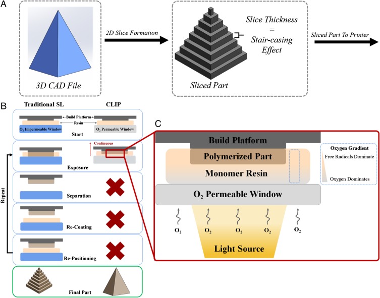
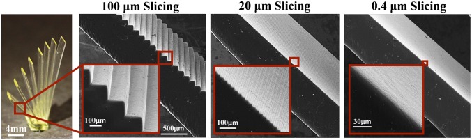
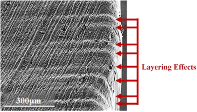
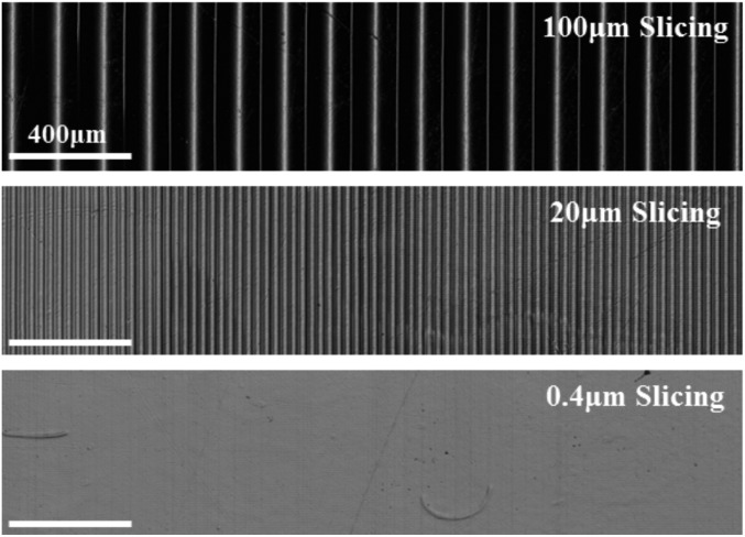
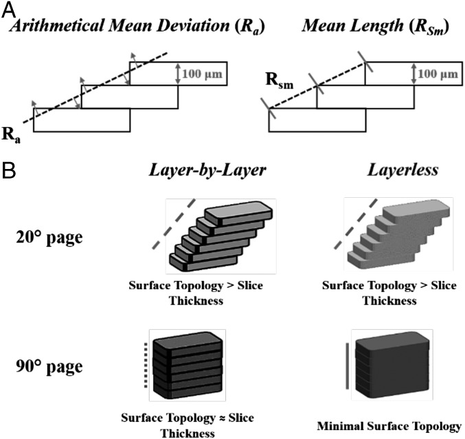
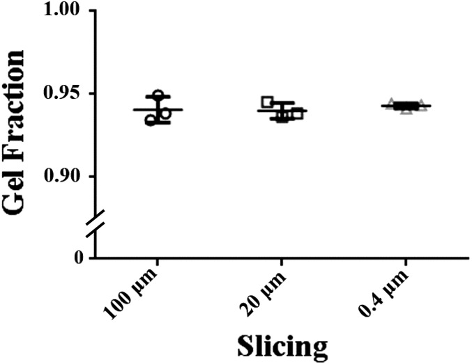
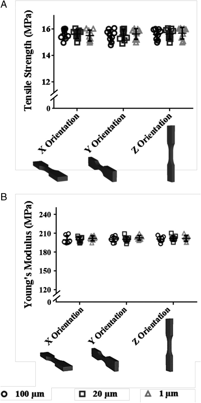
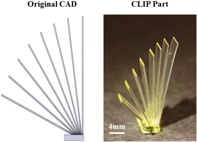
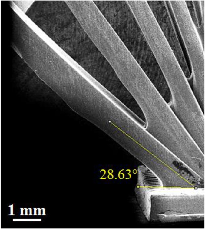
Despite the increasing popularity of 3D printing, also known as additive manufacturing (AM), the technique has not developed beyond the realm of rapid prototyping. This confinement of the field can be attributed to the inherent flaws of layer-by-layer printing and, in particular, anisotropic mechanical properties that depend on print direction, visible by the staircasing surface finish effect. Continuous liquid interface production (CLIP) is an alternative approach to AM that capitalizes on the fundamental principle of oxygen-inhibited photopolymerization to generate a continual liquid interface of uncured resin between the growing part and the exposure window. This interface eliminates the necessity of an iterative layer-by-layer process, allowing for continuous production. Herein we report the advantages of continuous production, specifically the fabrication of layerless parts. These advantages enable the fabrication of large overhangs without the use of supports, reduction of the staircasing effect without compromising fabrication time, and isotropic mechanical properties. Combined, these advantages result in multiple indicators of layerless and monolithic fabrication using CLIP technology.

Keywords: 3D printing; additive manufacturing; continuous liquid interface production; isotropic properties; stereolithogaphy.


Conflict of interest statement

J.R.T. and J.M.D. have an equity stake in Carbon, Inc., which is a venture-backed manufacturer of continuous liquid interface production equipment. Continuous liquid interface production is the subject of patent protection including issued US patents 9,205,601, 9,211,678, and 9,216,546.

Figures

Fig. 1.
Fig. 1.
Basic step comparison of traditional SL to CLIP. (A) Generation and slicing of a 3D CAD file are necessary steps for both the SL and CLIP platforms. (B) Traditional SL requires five fundamental steps to print a part: build elevator placement on resin (i), UV exposure to selectively cure resin (ii), separation of cured resin from the O2-impermeable window (iii), mechanical recoating of resin (iv), and, finally, repositioning of the build elevator (v) to repeat the process until the part is fully printed. CLIP uses a constant liquid interface enabled by the O2-permeable window, which eliminates the need for steps (ii, iii, and iv). (C) Schematic of the dead zone (DZ) produced by the presence of oxygen and the generation of free radicals upon UV exposure. Within the DZ there exists a concentration gradient of O2 whereas within the bulk there exist gradient light intensity and, to some degree, conversion before vitrification (34).
Fig. 2.
Fig. 2.
Open book benchmark fabricated with changing slicing conditions. ESEM micrographs obtained by imaging the 20° page of the open book benchmark under the three slice thicknesses.
Fig. S1.
Fig. S1.
ESEM micrograph of a part fabricated with the random layering effects highlighted. The part input slicing was 0.4 μm; however, instead of resulting in a smooth slope, layering effects are observed, which is indicative of the use of nonideal CLIP parameters in which the dead zone was depleted.
Fig. 3.
Fig. 3.
Intensity images of the open book benchmark obtained with OLS noncontact profilometry. A scanning laser was used to obtain intensity profiles of the 20° page of the open book as a function of slice thickness. Laser intensity corresponds to part height where the darker regions are lower than the lighter regions. The total scanned length was held constant.
Fig. 4.
Fig. 4.
Illustrations of theoretical differences in surface topology induced by AM technique. (A) Illustration of the two surface roughness parameters used in topological analysis. (B) The theoretical surface topological effects imparted by a layer-by-layer (SL) and a layerless (CLIP) fabrication approaches. The 20° for both approaches should theoretically yield similar surface effects. Therefore, the 90° page is the defining feature between layered and layerless fabrication due to its respective dependence and independence on input slice thickness.
Fig. S4.
Fig. S4.
Gel fraction analysis of CLIP open book benchmarks fabricated with slice thickness of 100, 20, and 0.4 μm. No statistical difference was found using one-way ANOVA among the slicing conditions.
Fig. 5.
Fig. 5.
Mechanical properties of fabricated parts. (A) Tensile strength as a function of printing orientation and slicing parameters with n = 9 per slicing condition per build orientation. (B) Young’s modulus as a function of printing orientation and slicing parameters with n = 9 slicing condition per build orientation. No statistical difference was found using one-way ANOVA among the slicing conditions or among the fabrication orientations.
Fig. S2.
Fig. S2.
Side-by-side comparison of open book benchmark. Original CAD file with page angles from 20° to 90° at 10° increments (Left) and CLIP-fabricated benchmark (Right).
Fig. S3.
Fig. S3.
Example angle measurement for the 20° page of the 0.4-µm-sliced open book benchmark.

References

    1. Huang SH, Liu P, Mokasdar A, Hou L. Additive manufacturing and its societal impact: A literature review. Int J Adv Manuf Technol. 2013;67(5–8):1191–1203.
    1. Lipson H, Kurman M. Fabricated : The New World of 3D Printing. Wiley; Somerset, NJ: 2013.
    1. Bartolo PJ. Stereolithography: Materials, Processes and Applications. Springer; New York: 2011.
    1. Sun C, Fang N, Wu DM, Zhang X. Projection micro-stereolithography using digital micro-mirror dynamic mask. Sens Actuators A Phys. 2005;121(1):113–120.
    1. Caulfield B, McHugh PE, Lohfeld S. Dependence of mechanical properties of polyamide components on build parameters in the SLS process. J Mater Process Technol. 2007;182(1–3):477–488.