. 2016 Oct:46:88-95.
doi: 10.1016/j.precisioneng.2016.04.003. Epub 2016 Apr 2.

Optical method for automated measurement of glass micropipette tip geometry

Affiliations

Optical method for automated measurement of glass micropipette tip geometry

Max A Stockslager et al. Precis Eng. 2016 Oct.

Abstract

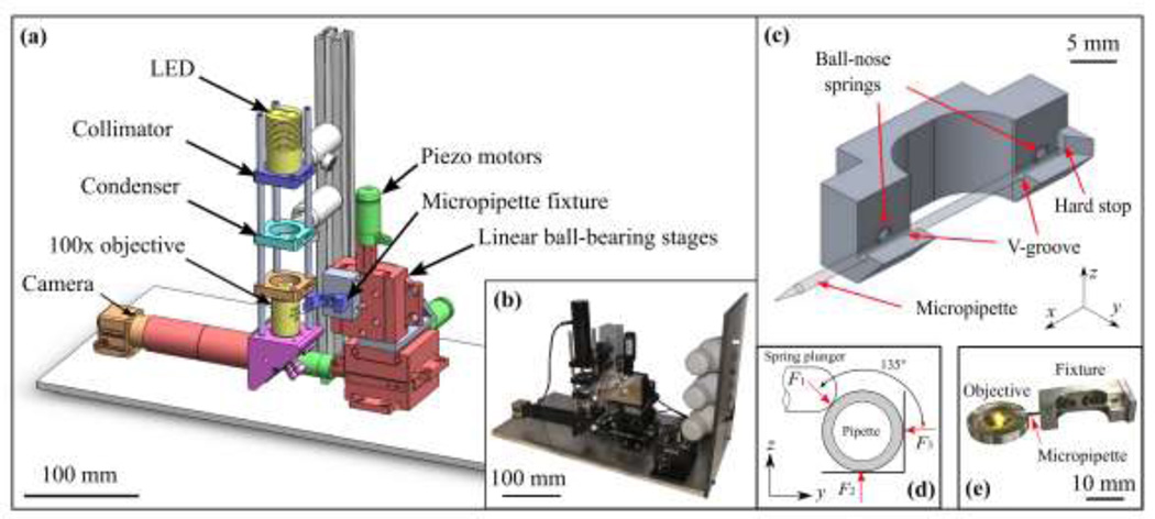
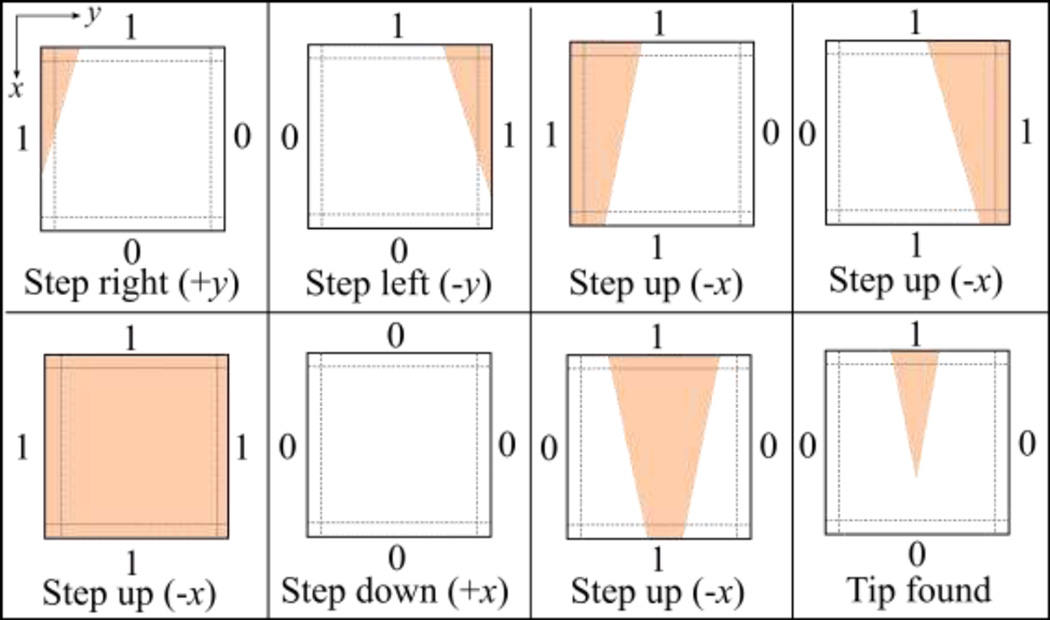
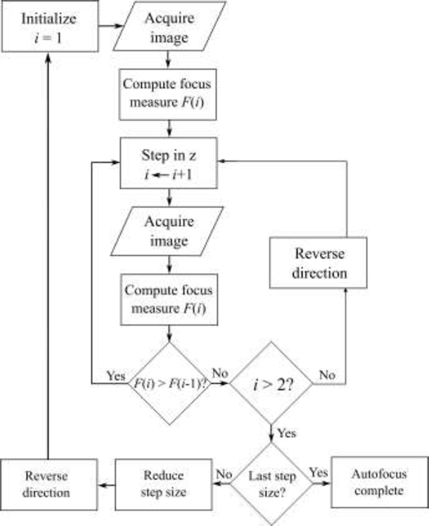
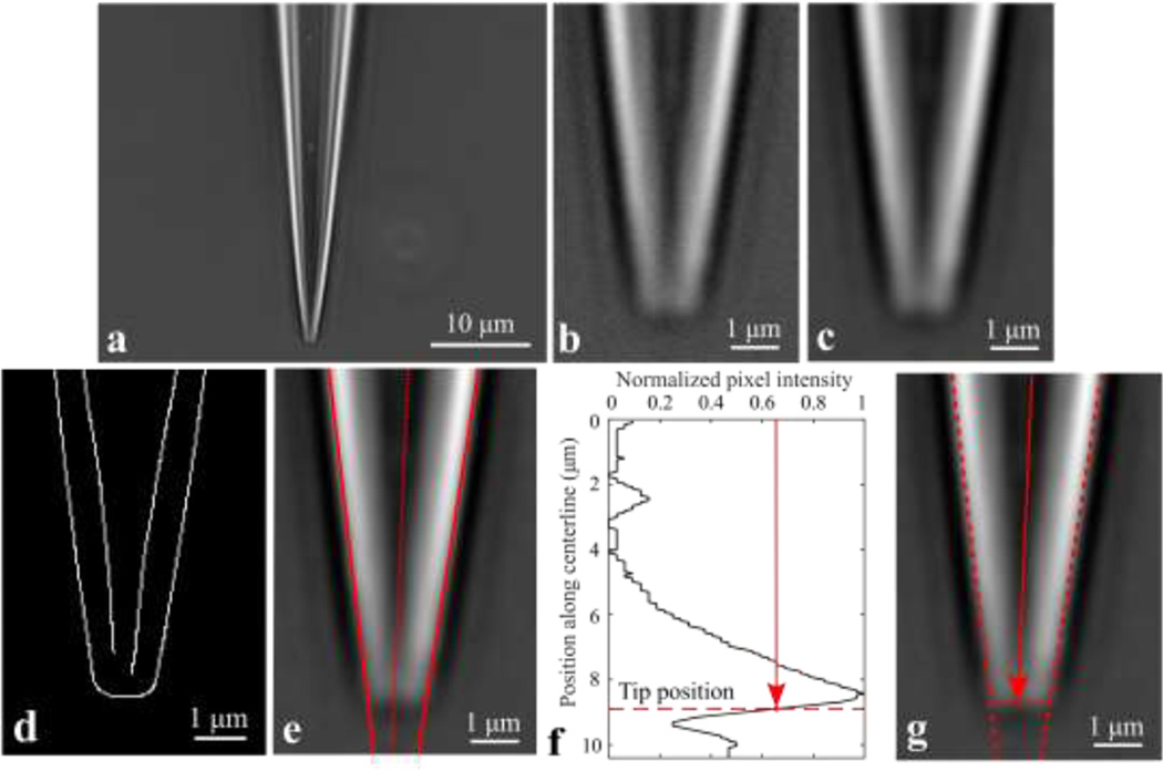
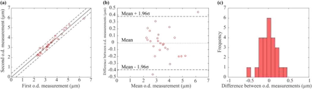
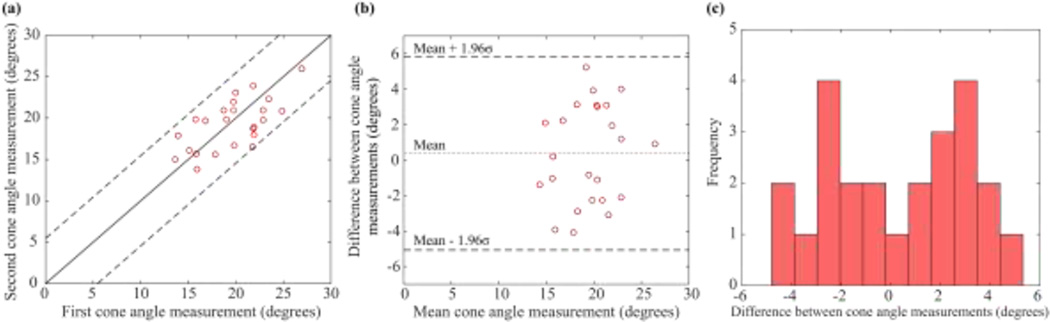
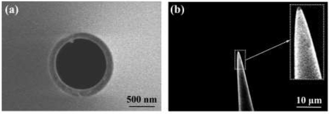
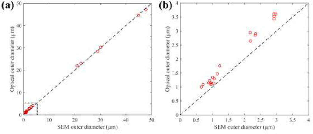
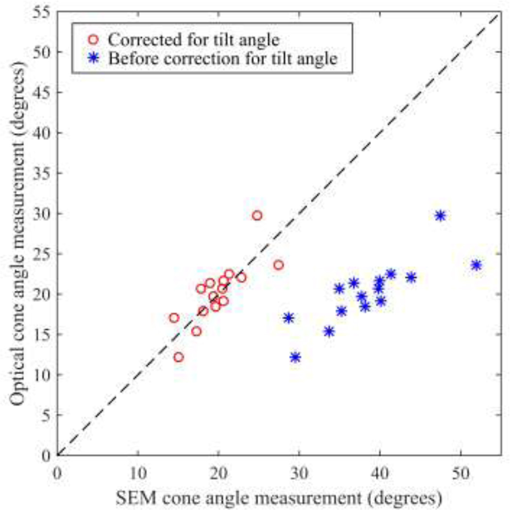
Many experimental biological techniques utilize hollow glass needles called micropipettes to perform fluid extraction, cell manipulation, and electrophysiological recordings For electrophysiological recordings, micropipettes are typically fabricated immediately before use using a "pipette puller", which uses open-loop control to heat a hollow glass capillary while applying a tensile load. Variability between manufactured micropipettes requires a highly trained operator to qualitatively inspect each micropipette; typically this is achieved by viewing the pipette under 40-100x magnification in order to ensure that the tip has the correct shape (e.g., outer diameter, cone angle, taper length). Since laboratories may use hundreds of micropipettes per week, significant time demands are associated with micropipette inspection. Here, we have automated the measurement of micropipette tip outer diameter and cone angle using optical microscopy. The process features repeatable constraint of the micropipette, quickly and automatically moving the micropipette to bring its tip into the field of view, focusing on the tip, and computing tip outer diameter and cone angle measurements from the acquired images by applying a series of image processing algorithms. As implemented on a custom automated microscope, these methods achieved, with 95% confidence, ±0.38 µm repeatability in outer diameter measurement and ±5.45° repeatability in cone angle measurement, comparable to a trained human operator. Accuracy was evaluated by comparing optical pipette measurements with measurements obtained using scanning electron microscopy (SEM); optical outer diameter measurements differed from SEM by 0.35 ± 0.36 µm and optical cone angle measurements differed from SEM by -0.23 ± 2.32°. The algorithms we developed are adaptable to most commercial automated microscopes and provide a skill-free route to rapid, quantitative measurement of pipette tip geometry with high resolution, accuracy, and repeatability. Further, these methods are an important step toward a closed-loop, fully-automated micropipette fabrication system.

Keywords: image processing; micropipette; microscope.


Figures

Fig. 1
Fig. 1
(a) Schematic of the automated microscope used for measurement of glass micropipette tip geometry, with (b) photograph of system as implemented. (c) Motorized fixture for kinematic constraint of the pipette, using a pair of ball-nose spring plungers to preload the pipette in aluminum V-grooves, resulting in (d) intersecting lines of force, which locate the center of stiffness along the axis of the pipette. Pipettes were constrained in y and z by the V-grooves and registered to a hard stop in the x direction. (e) Photograph of fixture as fabricated positioning a pipette over the objective.
Fig. 2
Fig. 2
Search strategy for the pipette tip-finding algorithm. Pipettes were repeatedly moved in 10 µm steps; the step direction was determined by detecting whether some part of the pipette was (1) or was not (0) present in a boundary region along each edge of the image. Pipettes were moved iteratively until the tip entered the field of view and the final condition (lower right) was encountered.
Fig. 3
Fig. 3
An autofocus algorithm captured pipette images, computed their Laplacian variance focus measure, and then moved the pipette accordingly to maximize focus. The pipette was moved in one direction until the focus measure crossed a local maximum, then the direction was reversed and the process was repeated with the next step size (sequentially: 20 µm, 5 µm, 2 µm, 0.5 µm) to obtain increasingly fine focus on the pipette tip.
Fig. 4
Fig. 4
A series of image processing computations were applied to identify the tip outer diameter and cone angle. Pipette tip images: (a) original; (b) cropped; (c) low-pass filtered; (d) Canny edge detection; (e) Hough transform lines and pipette centerline. (f) Normalized intensity of pixels along the pipette centerline, with the axial position corresponding to the tip labeled. (g) Image of pipette tip, with the diameter taken as the separation between the two outer Hough lines at the tip position from (f).
Fig. 5
Fig. 5
(a) Results of repeated outer diameter measurements on twenty-seven pipettes. (b) With 95% confidence, the first and second measurements differed by less than 0.38 µm. (c) The distribution of the difference between repeated measurements appeared normal.
Fig. 6
Fig. 6
(a) Results of repeated cone angle measurements on twenty-seven pipettes. (b) With 95% confidence, the first and second measurements differed by less than 5.45°, making the conservative approximation that errors were normally distributed; however, (c) errors were in fact bimodally distributed.
Fig. 7
Fig. 7
Scanning electron microscopy was used to evaluate accuracy of tip outer diameter and cone angle measurements obtained using our optical method. (a) Representative SEM image with no tilt, used to measure outer diameter. (b) Representative SEM image with 30° tilt, used to measure cone angle.
Fig. 8
Fig. 8
(a) Optical diameter measurements differed from SEM by 0.35 ± 0.36 µm across a wide range of diameters (0–50 µm). (b) For the subset of small (0–3 µm o.d.) micropipettes, optical diameter measurements differed from SEM by 0.40 ± 0.19 µm.
Fig. 9
Fig. 9
Comparison of cone angle measurements obtained using SEM and using our optical method. The dashed line indicates 1-1 agreement. Correcting for the tilt in the SEM image (using Eq. 3) improved agreement. Optical cone angle measurements differed from corrected SEM measurements by −0.23 ± 2.32°.

References

    1. Dean D, Gasiorowski J. Imaging, A Laboratory Manual. New York: CSHL Press; 2010. Preparing injection pipettes on a Flaming/Brown pipette puller. - PubMed
    1. Oesterle A. Pipette Cookbook 2015: P-97 & P-1000 Micropipette Pullers. California: Sutter Instrument; 2015.
    1. Kodandaramaiah S, Franzesi G, Chow B, Boyden ES, Forest CR. Automated whole-cell patch clamp electrophysiology of neurons in vivo . Nature Methods. 2012;9:585–587. - PMC - PubMed
    1. Flaming D. Method and Apparatus for Forming a Micropipette with Uniform Application of Heat. 4,921,522 US Patent. 1990
    1. Pak N, Dergance MJ, Emergick MT, Gagnon EB, Forest CR. An instrument for controlled, automated production of micrometer scale fused silica pipettes. J Mech Des. 2011:133.