. 2016 Sep 23;2(9):e1601014.
doi: 10.1126/sciadv.1601014. eCollection 2016 Sep.

Mechanical assembly of complex, 3D mesostructures from releasable multilayers of advanced materials

Affiliations

Mechanical assembly of complex, 3D mesostructures from releasable multilayers of advanced materials

Zheng Yan et al. Sci Adv. .

Abstract

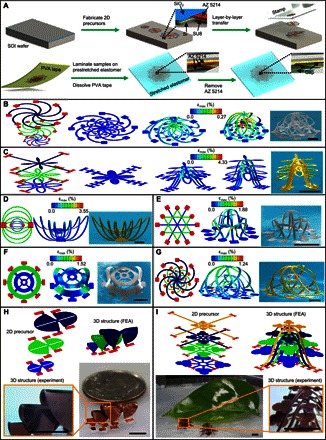
Capabilities for assembly of three-dimensional (3D) micro/nanostructures in advanced materials have important implications across a broad range of application areas, reaching nearly every class of microsystem technology. Approaches that rely on the controlled, compressive buckling of 2D precursors are promising because of their demonstrated compatibility with the most sophisticated planar technologies, where materials include inorganic semiconductors, polymers, metals, and various heterogeneous combinations, spanning length scales from submicrometer to centimeter dimensions. We introduce a set of fabrication techniques and design concepts that bypass certain constraints set by the underlying physics and geometrical properties of the assembly processes associated with the original versions of these methods. In particular, the use of releasable, multilayer 2D precursors provides access to complex 3D topologies, including dense architectures with nested layouts, controlled points of entanglement, and other previously unobtainable layouts. Furthermore, the simultaneous, coordinated assembly of additional structures can enhance the structural stability and drive the motion of extended features in these systems. The resulting 3D mesostructures, demonstrated in a diverse set of more than 40 different examples with feature sizes from micrometers to centimeters, offer unique possibilities in device design. A 3D spiral inductor for near-field communication represents an example where these ideas enable enhanced quality (Q) factors and broader working angles compared to those of conventional 2D counterparts.

Keywords: 3D Assembly; buckling; microfabrication; multilayer; near field communication.


Figures

Fig. 1
Fig. 1. Process for deterministic assembly of 3D mesostructures from releasable, multilayer, 2D precursors and illustrative examples.
(A) Schematic illustration of the procedures for fabricating 3D multilayer mesostructures in silicon by layer-by-layer transfer printing. (B) Exploded view of the three precursor layers, FEA results that describe the formation of 3D trilayer nested cages in silicon, and corresponding SEM image (colorized) of the final configuration. (C) Similar results for a 3D trilayer microstructure in epoxy that resembles a tree. (D to G) Multilayer 2D precursors, FEA predictions for the 3D mesostructures, and corresponding SEM image for bilayer nested saddles of epoxy (D), bilayer nested boxes of silicon (E), bilayer nested membranes of silicon (F), and hybrid trilayer nested cages of epoxy and silicon (G). (H and I) Exploded view of the various precursor layers, FEA predictions for 3D mesostructures made of bilayers consisting of copper (1 μm) and polyethylene terephthalate (PET) (50 μm), and corresponding optical images for a “Sydney Opera House” (H) and a four-layer “tree” (I). The color in the FEA results of (B) to (G) corresponds to the magnitude of maximum principal strain. Scale bars, 400 μm (B to G) and 4 mm (H and I).
Fig. 2
Fig. 2. Experimental and computational studies of various multilayer structures with assisting features.
(A) Multilayer 2D precursors, FEA predictions, and experimental images (SEM or optical) of the partially and fully assembled 3D structures for eight designs formed with the use of biaxial prestrain in the substrate. The first mesostructure is made of PI (green), the second one is made of PI (green) and copper/PI bilayers (orange), the third structure is made of epoxy (SU8, yellow), the fourth and fifth mesostructures are made of copper/PI bilayers, and the last three structures are made of plastic films. The red color in the 2D precursors denotes the bonding sites, and the gray color denotes the creases with reduced thickness than the other regions. (B) Schematic illustration and computed results for the folding angle and normal contact force as a function of prestrain for the 3D cube and pyramid in (A). (C) Multilayer 2D precursors, the FEA prediction of the 3D structures made of bilayers consisting of copper (1 μm) and PET (50 μm), and the corresponding experimental image (optical) for partially collapsed arrays of Dominoes with a straight path. (D) Similar results for partially collapsed arrays of Dominoes with a curved path. Scale bars, 600 μm [first five structures in (A)], 20 mm [last three structures in (A)], and 5 mm (C and D).
Fig. 3
Fig. 3. Process of deterministic assembly of 3D structures from interwoven, multilayer, 2D precursors and illustrative examples.
(A) Schematic illustration of the procedures for fabricating 3D interwoven multilayer structures of Cu/PET or Cu/PI bilayers by mechanical cutting techniques. (B and C) FEA predictions and SEM images of two multilayer mesostructures in bilayers of copper (9 μm) and PI (12 μm) with interwoven configurations. (D and E) FEA predictions and optical images of two multilayer structures in bilayers of copper (1 μm) and PET (50 μm) with interwoven configurations. Scale bars, 3 mm.
Fig. 4
Fig. 4. Experimental and computational studies of various 3D structures with coherently coupled multilayers via selective bonding.
(A) Schematic illustration of the assembly process of 3D structures from 2D precursors with coherently coupled multilayers that are bonded with each other at selective sites. (B) Multilayer 2D precursors from the top and cross-sectional views, FEA predictions, and optical images for six multilayer structures formed with the use of uniaxial prestrain in the substrate. (C) FEA predictions and optical images of five multilayer structures formed with the use of biaxial prestrain in the substrate. The last two structures in (B) are made of plastic films with two different thicknesses (40 μm for the bottom two layers and 25 μm for the top two layers). The other structures are all made of bilayers of copper (1 μm) and PET (50 μm), except for the second structure in (C), which consists of the same bilayers at the first floor and bilayers of copper (12 μm) and PI (12 μm) at the second floor. Scale bars, 5 mm.
Fig. 5
Fig. 5. A 3D NFC device with enhanced Q factor and improved working angle over conventional 2D counterparts.
(A) Schematic illustration of the multilayer 2D precursors, an exploded view to show the layer construction, and the corresponding 3D configurations (optical image, right top; FEA results, right bottom) with the use of uniaxial prestrain (εx-appl = 70% and εy-appl = 0%). Scale bars, 2 mm. (B) Measured and computed dependence of the Q factor and inductance on the applied strain for devices with two different widths (1.03 and 2.00 mm) in the supporting ribbon. The right frame corresponds to the FEA results of 3D configurations for the NFC device under different levels of applied strain (0, 20, and 70%). The other geometric parameters are fixed as wcoil = 222 μm (coil width), s = 82 μm (coil spacing), and nturn = 12 (turn number). (C) Measured and computed results for the Q factor and inductance versus the width of supporting ribbon for both the 2D and 3D devices with wcoil = 222 μm, s = 82 μm, and nturn = 12. (D) Computed results of the induced voltage as a function of the working angle and the applied strain, when the devices are coupled with a commercial primary coil, as schematically shown in the right top frame. A capacitor (152 pF for 2D and 182.5 pF for 3D in the left frame; 182.5 pF in the middle frame) is used for impedance matching. The right bottom frame corresponds to an optical image demonstrating the use of the 3D NFC device for lighting a commercial red LED. The geometric parameters adopted in the calculations include wribbon = 2.00 mm, wcoil = 222 μm, s = 82 μm, and nturn = 12. (E) Computed Q factor versus the metal thickness (left, with wribbon = 1.84 mm, wcoil = 222 μm, s = 84 μm, and nturn = 12), turn number (middle, with wribbon = 1.84 mm, wcoil = 222 μm, s = 84 μm, and tcu = 9 μm), and the width of coil (right, with wribbon = 1.84 mm, s = 84 μm, tcu = 9 μm, and nturn = 12).

References

    1. Rogers J., Huang Y., Schmidt O. G., Gracias D. H., Origami MEMS and NEMS. MRS Bull. 41, 123–129 (2016).
    1. Tian B., Liu J., Dvir T., Jin L., Tsui J. H., Qing Q., Suo Z., Langer R., Kohane D. S., Lieber C. M., Macroporous nanowire nanoelectronic scaffolds for synthetic tissues. Nat. Mater. 11, 986–994 (2012). - PMC - PubMed
    1. Leong T. G., Randallb C. L., Bensona B. R., Bassika N., Sterna G. M., Gracias D. H., Tetherless thermobiochemically actuated microgrippers. Proc. Natl. Acad. Sci. U.S.A. 106, 703–708 (2009). - PMC - PubMed
    1. Yu M. R., Huang Y., Ballweg J., Shin H., Huang M., Savage D. E., Lagally M. G., Dent E. W., Blick R. H., Williams J. C., Semiconductor nanomembrane tubes: Three-dimensional confinement for controlled neurite outgrowth. ACS Nano 5, 2447–2457 (2011). - PMC - PubMed
    1. Feiner R., Engel L., Fleischer S., Malki M., Gal I., Shapira A., Shacham-Diamand Y., Dvir T., Engineered hybrid cardiac patches with multifunctional electronics for online monitoring and regulation of tissue function. Nat. Mater. 15, 679–685 (2016). - PMC - PubMed