. 2017 Feb;45(2):496-507.
doi: 10.1007/s10439-016-1734-z. Epub 2016 Oct 3.

Ex Vivo Methods for Informing Computational Models of the Mitral Valve

Affiliations

Ex Vivo Methods for Informing Computational Models of the Mitral Valve

Charles H Bloodworth 4th et al. Ann Biomed Eng. 2017 Feb.

Abstract

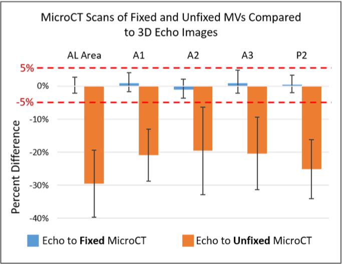
Computational modeling of the mitral valve (MV) has potential applications for determining optimal MV repair techniques and risk of recurrent mitral regurgitation. Two key concerns for informing these models are (1) sensitivity of model performance to the accuracy of the input geometry, and, (2) acquisition of comprehensive data sets against which the simulation can be validated across clinically relevant geometries. Addressing the first concern, ex vivo micro-computed tomography (microCT) was used to image MVs at high resolution (~40 micron voxel size). Because MVs distorted substantially during static imaging, glutaraldehyde fixation was used prior to microCT. After fixation, MV leaflet distortions were significantly smaller (p < 0.005), and detail of the chordal tree was appreciably greater. Addressing the second concern, a left heart simulator was designed to reproduce MV geometric perturbations seen in vivo in functional mitral regurgitation and after subsequent repair, and maintain compatibility with microCT. By permuting individual excised ovine MVs (n = 5) through each state (healthy, diseased and repaired), and imaging with microCT in each state, a comprehensive data set was produced. Using this data set, work is ongoing to construct and validate high-fidelity MV biomechanical models. These models will seek to link MV function across clinically relevant states.

Keywords: Cardiovascular; Imaging; Micro-computed tomography; Mitral regurgitation; Mitral repair; Simulation.


Figures

FIGURE 1
FIGURE 1
(A) The Cylindrical Left Heart Simulator (CLHS) features acrylic left atrial (LA) and left ventricular (LV) chambers. An ovine mitral valve (MV) is excised and mounted to the annular plate separating the two compartments. Rods are used to manipulate the positions of the papillary muscles (PMs). (B) The CLHS is inserted into a pulsatile flow loop. A bladder pump is used to drive physiological flows and pressured in the CLHS. Systemic compliance and resistance elements are used to tune the pressure and flow profiles. Pressures and flows are monitored and recorded, along with 3D echo images if the MV.
FIGURE 2
FIGURE 2
Design of the customized annular MV attachment plate to manipulate annular geometry. (A) Computer aided design of the assembly before annular dilatation. Five actuating plastic segments along the posterior aspect of the mitral annulus travel along worm-screw drives seated within the rigid plate. The arrows are overlaid on the segments along the posterior aspect of the annulus. Shown in (B), the position of the segments is adjusted from the outer circumference to pull the segments radially outward to achieve the dilated geometry. Additionally, along the anterior aspect of the annulus, a flexible, laser-cut plastic sheet (orange part directly under green circles) is mounted at the anterior horn. Two wedges, highlighted in green circles, are adjusted to drive the flexible plate apically out of the page at the commissures to achieve a saddle-shaped annular geometry. (C) The final assembly is shown with a black elastic sealing membrane and retainer ring.
FIGURE 3
FIGURE 3
Flow chart detailing the order in which data was collected using the methodologies presented, producing comprehensive data sets for model construction and validation.
FIGURE 4
FIGURE 4
(A) Side view of the mitral leaflets and sub-valvular apparatus of a mitral valve loaded at 100mmHg and imaged by microCT. (B) Using the fiducial marker grid and equation (1), anterior leaflet areal green strain was computed with the diastolic microCT scan as the reference configuration, and is overlaid on the systolic MV model. Average strain in the belly region was found to be 47.1±21.5%. Average strain in the coaptation zone was found to be - 12.5±15.8%.
FIGURE 5
FIGURE 5
The adhesive/cohesive effect of residual water on the MV is shown here. (A) An image of the MV in the CLHS after water has been drained reveals that the thin marginal leaflet tissue folds on itself and the chordal trees bunch together. (B) When the MV is submerged in water, the chordal detail is visible and the anterior leaflet is appreciably larger.
FIGURE 6
FIGURE 6
A vertical, steady flow loop is used to apply glutaraldehyde fixative. After microCT scans in the loaded condition are taken, the cylindrical left heart simulator (CLHS) is mounted vertically into the loop shown here. The leaflets spread and hang normal to the annular plane as glutaraldehyde solution (0.5% in deionized water) fixes the leaflets in place, yielding a repeatable, anatomical diastolic MV geometry.
FIGURE 7
FIGURE 7
Annular measurements of the custom annulus plate are made with microCT images in post-processing. (A) For the healthy geometry, Commissural Width (CWH) and Anterior-Posterior diameter (APH) are shown with green arrows while the total annular area (A) is shown within the blue line. (B) The same (CW, AP, A) are shown for the IMR/Diseased annular geometry. (C) The annular height (AH) from plane of the annulus is shown for the healthy geometry. Note that the repaired state simulates a flat annuloplasty ring, and therefore has the same annular areal measurements as the healthy geometry, without the 3D saddle shape.
FIGURE 8
FIGURE 8
Models segmented from microCT images of the same representative MV with- and without fixation. (A) Without fixation, the detail within the folded and bunched structures cannot be distinguished; the leaflet area is under-represented and the chordal trees lack any detail or definition. (B) After glutaraldehyde fixation is performed, the resulting model shows preserved leaflet area and chordal detail. The individual marginal chordae and undulations in the mitral leaflets are captured with high contrast and resolution.
FIGURE 9
FIGURE 9
Achieved papillary muscle displacement values for the posteromedial and anterolateral papillary muscles (PMPM and ALPM, respectively) measured by microCT compared with target values based on in vivo data. Displacements for the PMPM and ALPM were found to be 6.2±1.0 mm and 2.5±1.3 mm respectively, as compared to values calculated from literature of 7.5 mm and 2.7 mm, respectively. No significant difference was found between the achieved and desired displacement values for the ALPM (p=0.9). However, that of the PMPM was found to be small, but significant (p=0.05).
FIGURE 10
FIGURE 10
MicroCT scans of each MV (n=5) in the diastolic state with- and without glutaraldehyde fixation are compared to the peak diastolic frame of 3D echo for the same MVs under pulsatile flow. Mean and 95% confidence interval are shown for the differences observed in identical measurements made on the diastolic microCT scan and on a mid-diastolic frame of 3D echo images. Anterior leaflet lengths (A1, A2, A2), posterior leaflet length (P2) and anterior leaflet area (Area) were all found to be equivalent to within ±5% with 95% confidence between the glutaraldehyde fixed images and the dynamic 3D echo images (p<0.05). Percent change of the above measurements from the 3D echo images to the unfixed microCT images was found to be significantly negative (p<.001), revealing substantial MV shrinkage in the range of 20-30% when imaging without fixation.

References

    1. Acker MA, Parides MK, Perrault LP, Moskowitz AJ, Gelijns AC, Voisine P, Smith PK, Hung JW, Blackstone EH, Puskas JD, Argenziano M, Gammie JS, Mack M, Ascheim DD, Bagiella E, Moquete EG, Ferguson TB, Horvath KA, Geller NL, Miller MA, Woo YJ, D'Alessandro DA, Ailawadi G, Dagenais F, Gardner TJ, O'Gara PT, Michler RE, Kron IL, Ctsn Mitral-valve repair versus replacement for severe ischemic mitral regurgitation. N Engl J Med. 2014;370:23–32. - PMC - PubMed
    1. Borger MA, Alam A, Murphy PM, Doenst T, David TE. Chronic ischemic mitral regurgitation: repair, replace or rethink? Ann Thorac Surg. 2006;81:1153–1161. - PubMed
    1. Braunberger E, Deloche A, Berrebi A, Abdallah F, Celestin JA, Meimoun P, Chatellier G, Chauvaud S, Fabiani JN, Carpentier A. Very long-term results (more than 20 years) of valve repair with carpentier's techniques in nonrheumatic mitral valve insufficiency. Circulation. 2001;104:I8–11. - PubMed
    1. Carpentier A, Adams DH, Filsoufi F. Carpentier's reconstructive valve surgery. Elsevier Health Sciences. 2011
    1. Daimon M, Saracino G, Fukuda S, Koyama Y, Kwan J, Song JM, Agler DA, Gillinov AM, Thomas JD, Shiota T. Dynamic change of mitral annular geometry and motion in ischemic mitral regurgitation assessed by a computerized 3D echo method. Echocardiography. 2010;27:1069–1077. - PubMed

MeSH terms