Dislocation Strengthening without Ductility Trade-off in Metastable Austenitic Steels
- PMID: 27739481
- PMCID: PMC5064382
- DOI: 10.1038/srep35345
Dislocation Strengthening without Ductility Trade-off in Metastable Austenitic Steels
Erratum in
-
Corrigendum: Dislocation Strengthening without Ductility Trade-off in Metastable Austenitic Steels.Sci Rep. 2018 Jan 29;8:46938. doi: 10.1038/srep46938. Sci Rep. 2018. PMID: 29376516 Free PMC article.
Abstract
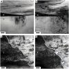
Strength and ductility are mutually exclusive if they are manifested as consequence of the coupling between strengthening and toughening mechanisms. One notable example is dislocation strengthening in metals, which invariably leads to reduced ductility. However, this trend is averted in metastable austenitic steels. A one-step thermal mechanical treatment (TMT), i.e. hot rolling, can effectively enhance the yielding strength of the metastable austenitic steel from 322 ± 18 MPa to 675 ± 15 MPa, while retaining both the formability and hardenability. It is noted that no boundaries are introduced in the optimized TMT process and all strengthening effect originates from dislocations with inherited thermal stability. The success of this method relies on the decoupled strengthening and toughening mechanisms in metastable austenitic steels, in which yield strength is controlled by initial dislocation density while ductility is retained by the capability to nucleate new dislocations to carry plastic deformation. Especially, the simplicity in processing enables scaling and industrial applications to meet the challenging requirements of emissions reduction. On the other hand, the complexity in the underlying mechanism of dislocation strengthening in this case may shed light on a different route of material strengthening by stimulating dislocation activities, rather than impeding motion of dislocations.
Figures


References
-
- Lu K., Lu L. & Suresh S. Strengthening Materials by Engineering Coherent Internal Boundaries at the Nanoscale. Science 324, 349–352 (2009). - PubMed
-
- Lu K. The Future of Metals. Science 328, 319–320 (2010). - PubMed
-
- Fang T. H., Li W. L., Tao N. R. & Lu K. Revealing Extraordinary Intrinsic Tensile Plasticity in Gradient Nano-Grained Copper. Science 331, 1587–1590 (2011). - PubMed
-
- Kou H., Lu J. & Li Y. High-Strength and High-Ductility Nanostructured and Amorphous Metallic Materials. Advanced Materials n/a-n/a (2014). - PubMed
Publication types
LinkOut - more resources
Full Text Sources
Other Literature Sources

