. 2016 Oct 20:6:35273.
doi: 10.1038/srep35273.

Long-Term Homeostatic Properties Complementary to Hebbian Rules in CuPc-Based Multifunctional Memristor

Affiliations

Long-Term Homeostatic Properties Complementary to Hebbian Rules in CuPc-Based Multifunctional Memristor

Laiyuan Wang et al. Sci Rep. .

Abstract

Most simulations of neuroplasticity in memristors, which are potentially used to develop artificial synapses, are confined to the basic biological Hebbian rules. However, the simplex rules potentially can induce excessive excitation/inhibition, even collapse of neural activities, because they neglect the properties of long-term homeostasis involved in the frameworks of realistic neural networks. Here, we develop organic CuPc-based memristors of which excitatory and inhibitory conductivities can implement both Hebbian rules and homeostatic plasticity, complementary to Hebbian patterns and conductive to the long-term homeostasis. In another adaptive situation for homeostasis, in thicker samples, the overall excitement under periodic moderate stimuli tends to decrease and be recovered under intense inputs. Interestingly, the prototypes can be equipped with bio-inspired habituation and sensitization functions outperforming the conventional simplified algorithms. They mutually regulate each other to obtain the homeostasis. Therefore, we develop a novel versatile memristor with advanced synaptic homeostasis for comprehensive neural functions.


Figures

Figure 1
Figure 1. Tunable conductivity under cyclic sweeps in the ITO/CuPc/Al memristor.
(a) Schematic diagram of the CuPc-based crossbar architecture and one typical CuPc element compared with a biological synapse on the right. The applied electrical inputs correspond to the synaptic action potentials. The thickness of the evaporated CuPc film is monitored by a quartz crystal cymometer Δf = 800 Hz (~50 nm). Device size: 100 × 100 μm2. (b) Memristive current under 10 cyclic voltage sweeps (0 → 11/−11 V → 0). (c) Polarity-dependent EPIR effect. The current progressively increases/decreases under a series of electrical pulses. (d) Tuning current curves with different sweeping amplitudes. The sweeping amplitude of the first two cycles is 10 V, and the third one is 11 V. (e) Current hysteresis curves at different scanning speeds, 0.2 V/s of the first 10 cycles and 0.02 V/s of the last two cycles. Inset shows the current tendency versus the cycle number. The increasing stride at the maximum voltage increases by ~5 times as the scanning rate is reduced tenfold. (f) Log-log plots of the forward scanning current extracted from (b). Inset shows the fitting slope of the first cyclic current curve. Backward curves nearly coincide with the following forward curves. Fitting results demonstrate that the current is trap-affected SCLC, and there exists a dominant SCLC region in each sweep (undergoing the maximum range) marked by the short bars. (g) Schematic diagram of the correlation between decreasing slopes of dominant SCLC during 10 forward sweeps in (f) and the gradual variation of exponentially distributed state density. More and more traps are filled by retentive charges, causing gradually reducing trap sites which can be measured by the integral area under each exponential curve.
Figure 2
Figure 2. Tunable conductive states of the ITO/MoO3/CuPc/Al memristor.
(a) 20 cyclic I-V characteristics under consecutive positive/negative voltage sweeps (0 → 6/−6 V → 0). (b) The trend in the current versus pulse number for the data shown in (a). (c) The decreasing slopes of the dominant SCLC during 20 positive forward sweeps in ITO/MoO3/CuPc/Al memristor.
Figure 3
Figure 3. Balanced memristive responses under coordinate stimuli.
(a) Schematic diagram of alternant excitatory and inhibitory inputting pulses applied to the ITO/MoO3/CuPc/Al device consisting of different number of positive/negative pulses Ne/Ni in each period. N is the number of applied periods. (b) The increasing/decreasing current under positive/negative pulses (Ve/Vi = 8/−8 V, 9/−9 V, 10/−10 V and Ne/Ni = 5). The right diagram shows the ultimate increment/decrement in different amplitude modes. The variations in low-voltage modes are unobvious. (c) The periodic increasing/decreasing current under the same periods of positive/negative pulses in three modes with different Ne/Ni (VeVi = 10/−10 V, N = 10). (d) The variations of the conductance (ΔG) (defined as ΔI/V) versus Ne/Ni in the typical periods of Fig. (c). (e) The corresponding synaptic weight (Δw) (defined as ΔG/G). (f ) Histogram of the time constants τ (calculated from the stretched exponential equation) of excitatory and inhibitory currents extracted from (e), and increasing formula image means that more time is required to reach the respective saturated values in different modes.
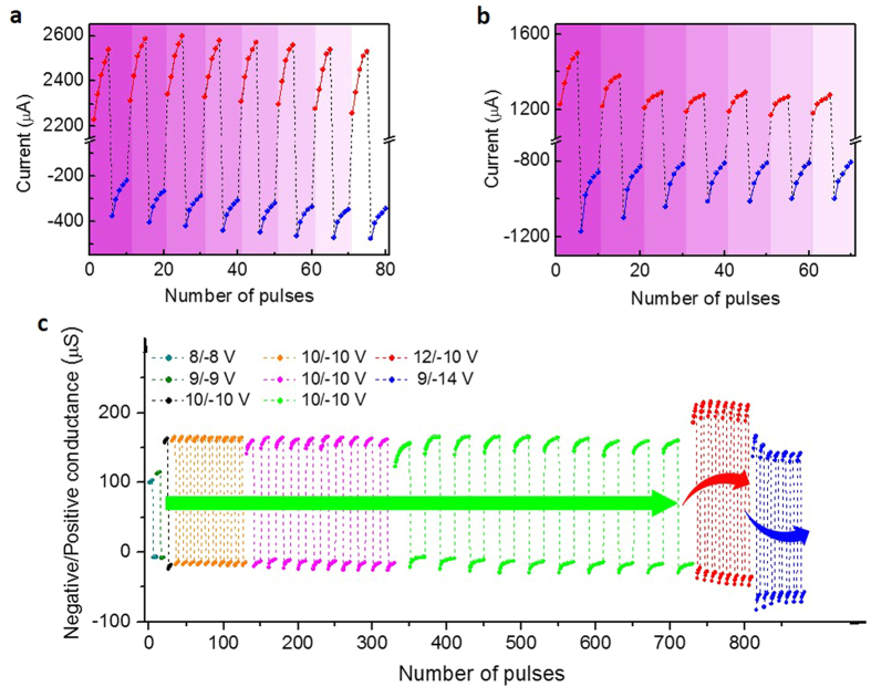
Figure 4
Figure 4. Homeostatic memristive responses under non-coordinated pulses.
(a,b) The current gradually increases/decreases under pulses of Ve/Vi = 12/−10 V a and 9/−14 V b. (a) Compared with the mode of Ve/Vi = 10/−10 V, the positive current grows stronger, while the overall negative level is gradually enhanced till they reach a homeostatic state as more periods are applied. (b) Greater non-equilibrium inputs enlarge the initial unbalanced states. The greater negative overall current gradually relaxes, while the overall positive level is gradually depressed till they reach a new stable balanced state. (c) The comprehensive comparisons of the overall positive and negative conductance and long-term regulatory changes in different Ve/Vi and Ne/Ni modes extracted from Figs 3b,c and 4a,b, respectively.
Figure 5
Figure 5. Tunable conductive states in thicker CuPc-based memristors.
(a,b) Gradually relaxing overall current in thicker memristors (Δf = 1600 Hz ~70 nm of (a) and 3200 Hz ~90 nm of (b), (Ne/Ni = 5, Ve/Vi = 10/−10 V, and N = 10). The current progressively increases/decreases under positive/negative pulses in each period, whereas the overall current gradually decreases as more periods are applied, and the relaxation trend is more obvious in (b) than in (a). Insets display schematic diagrams of thicker memristors (1600 Hz (a) 3200 Hz (b).
Figure 6
Figure 6. Habituation and sensitization behaviours.
(af) As periodically alternant stimuli are applied, the current gradually increases/decreases under 5 pulses of 6/−6 V (a,c,e,g), 8/−8 V (b), 10/−10 V (d) 12/−12 V (f ) in an ITO/MoO3/CuPc (3200Hz)/Al memristor. The applied stimuli are further illustrated in Fig. S9b. (a) The overall average current gradually decreases under modest inputs. However, the excitatory level is gradually enhanced under strong stimuli (b) and the current after being motivated by sensitive pulses is higher than before (c). The stronger sensitive pulses are (b,d,f ) the higher excitatory levels are reached under both sensitive and following habitual actions (a,c,e,g). The sequential habituation and sensitization in (af ) are labelled as H1, S1, H2, S2, H3 and S3 stages, respectively. (g) Refractory period. After applying intense pulses (f ) the current cannot be immediately excited by the first 5 modest pulses (red region). (h) The average excitatory current under intense pulses slowly relaxes as more periods are applied (Ve/Vi = 10/−10 V). (i) Graphical auditory responses of habituation and sensitization in H1, S1, H2, S2, H3, and S3 stages extracted from (af ). Assuming that the periodic habitual and sensitive inputs in different stages with different amplitudes correspond to a series of voices with different intensities entering the auditory system marked by the character “i” with different colour depths, and the overall conductance corresponds to the auditory response marked by the red bars with different intensities and depths.

Similar articles

Cited by

References

    1. Jo S. H. et al. Nanoscale memristor device as synapse in neuromorphic systems. Nano Lett. 10, 1297–1301 (2010). - PubMed
    1. Linares-Barranco B. & Serrano-Gotarredona T. Memristance can explain spike-time-dependent-plasticity in neural synapses. Nature precedings 1, 1–4 (2009).
    1. Prezioso M. et al. Training and operation of an integrated neuromorphic network based on metal-oxide memristors. Nature 521, 61–64 (2015). - PubMed
    1. Mahowald M. & Douglas R. A silicon neuron. Nature 354, 515–518 (1991). - PubMed
    1. Lai Q. et al. Ionic/electronic hybrid materials integrated in a synaptic transistor with signal processing and learning functions. Adv. Mater. 22, 2448–2453 (2010). - PubMed

Publication types