. 2016 Nov;148(5):405-418.
doi: 10.1085/jgp.201611672. Epub 2016 Oct 17.

The Hv1 proton channel responds to mechanical stimuli

Affiliations

The Hv1 proton channel responds to mechanical stimuli

Medha M Pathak et al. J Gen Physiol. 2016 Nov.

Abstract

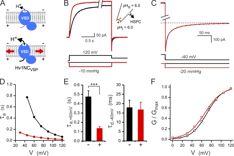
The voltage-gated proton channel, Hv1, is expressed in tissues throughout the body and plays important roles in pH homeostasis and regulation of NADPH oxidase. Hv1 operates in membrane compartments that experience strong mechanical forces under physiological or pathological conditions. In microglia, for example, Hv1 activity is potentiated by cell swelling and causes an increase in brain damage after stroke. The channel complex consists of two proton-permeable voltage-sensing domains (VSDs) linked by a cytoplasmic coiled-coil domain. Here, we report that these VSDs directly respond to mechanical stimuli. We find that membrane stretch facilitates Hv1 channel opening by increasing the rate of activation and shifting the steady-state activation curve to less depolarized potentials. In the presence of a transmembrane pH gradient, membrane stretch alone opens the channel without the need for strong depolarizations. The effect of membrane stretch persists for several minutes after the mechanical stimulus is turned off, suggesting that the channel switches to a "facilitated" mode in which opening occurs more readily and then slowly reverts to the normal mode observed in the absence of membrane stretch. Conductance simulations with a six-state model recapitulate all the features of the channel's response to mechanical stimulation. Hv1 mechanosensitivity thus provides a mechanistic link between channel activation in microglia and brain damage after stroke.


Figures

Figure 1.
Figure 1.
Hv1 response to combined electrical and mechanical stimulation. (A) Schematic representation of dimeric Hv1 stimulated by membrane stretch (red arrows). (B) Effect on Hv1 activation: Proton currents were measured in response to membrane depolarization in the absence (black) and presence (red) of negative pressure in the pipette. Holding potential: −80 mV, holding pressure: 0 mmHg. (C) Effect on Hv1 deactivation: Tail currents were measured at −40 mV after a depolarization pulse at 120 mV in the absence (black) and presence (red) of negative pressure in the pipette. Holding conditions and proton concentrations were as in B. Dotted line corresponds to 0 pA. Break in the current axis corresponds to 200 pA. (D) τa as a function of applied voltage without pressure stimulation (black circles) and in the presence of −10 mmHg pressure in the pipette (red squares). (E, left) Effect of −10-mmHg-pressure stimulation on τa measured at 60 mV; n = 11; ***, P < 0.0001. (right) Effect of −20-mmHg-pressure stimulation on τd measured at −40 mV; n = 3; P > 0.05. (F) Effect on G-V curve of negative pressure in the pipette. G-Vs measured at 0 mmHg and −10 mmHg are shown in black and red, respectively. Boltzmann fit parameters are V1/2 = 60.5 ± 1.5 mV and s = 11.0 ± 0.8 mV for the 0-mmHg condition (n = 10) and V1/2 = 46.1 ± 1.2 mV and s = 7.5 ± 0.4 mV for the −10-mmHg condition (n = 10). P < 10−6 and P < 0.002 for differences in V1/2 and s, respectively. Errors bars are SEM.
Figure 2.
Figure 2.
Hv1NCVSP response to combined electrical and mechanical stimulation. (A) Schematic representation of monomeric Hv1NCVSP stimulated by membrane stretch (red arrows). (B) Effect on Hv1NCVSP activation: Proton currents were measured in response to membrane depolarization in the absence (black) and presence (red) of negative pressure in the pipette. Holding potential: −80 mV, holding pressure: 0 mmHg. Break in the time axis corresponds to 1.5 s. (C) Effect on Hv1NCVSP deactivation: Tail currents were measured at −40 mV after a depolarization pulse at 120 mV in the absence (black) and presence (red) of negative pressure in the pipette. Holding conditions and proton concentrations were as in B. Dotted line corresponds to 0 pA. Break in the current axis corresponds to 650 pA. (D) τa values measured as a function of applied voltage without pressure stimulation (black circles) and in the presence of −10 mmHg pressure in the pipette (red squares). (E, left) Effect of −10-mmHg-pressure stimulation on τa measured at 60 mV; n = 14; ***, P < 0.0001. (right) Effect of −20-mmHg-pressure stimulation on τd measured at −40 mV; n = 5; P > 0.05. (F) Effect on G-V curve of negative pressure in the pipette. G-Vs measured at 0 mmHg and −10 mmHg are shown in black and red, respectively. Boltzmann fit parameters are V1/2 = 70.9 ± 0.7 mV and s = 16.1 ± 0.4 mV for the 0-mmHg condition (n = 26) and V1/2 = 66.4 ± 1.0 mV and s = 18.1 ± 0.4 mV for the −10-mmHg condition (n = 26). P < 0.001 and P < 0.002 for differences in V1/2 and s, respectively. Errors bars are SEM. In F, error bars are smaller than symbols.
Figure 3.
Figure 3.
Effects of brief mechanical stimulation on Hv1 activation. (A) Hv1 current was elicited by membrane depolarization as in Fig. 1 B and measured in the absence of mechanical stimulation (black) and in the presence of a brief pulse of negative pressure in the pipette (red). The pulse was delivered when the fraction of open channels generated by voltage-dependent activation was still small. See Materials and methods for details. (B) Enlarged view of current traces (I) enclosed in the blue square in A. Pressure traces recorded during stimulation are also shown (P). (C) Hv1 currents were measured as in A, but with the mechanical stimulus delivered when voltage-dependent activation had produced a larger fraction of open channels. (A and C) Inset bar charts indicate the mean relative increase in current measured at the end of the pulse (EP) and the mean residual increase in current measured at the end of the depolarization step (ED). Error bars are SEM (n = 5). (D) Enlarged view of current traces (I) enclosed in the blue square in C and corresponding pressure traces (P). Black arrowheads in A and C indicate difference in isochronal current at the end of the two traces (ED > 0). Red, blue, and gray arrowheads in B and D indicate different components of the effect of mechanical stimulation on Hv1 activation.
Figure 4.
Figure 4.
Effects of brief mechanical stimulation on Hv1NCVSP activation. (A) Hv1NCVSP current was elicited by membrane depolarization as in Fig. 2 B and measured in the absence of mechanical stimulation (black) and in the presence of a brief pulse of negative pressure in the pipette (red). The pulse was delivered when the fraction of open channels generated by voltage-dependent activation was still small. See Materials and methods for details. (B) Enlarged view of current traces (I) enclosed in the blue rectangle in A. Pressure traces recorded during stimulation are also shown (P). (C) Hv1 currents were measured as in A, but with the mechanical stimulus delivered when voltage-dependent activation had produced a larger fraction of open channels. (A and C) Inset bar chart indicates the mean relative increase in current measured at the end of the pulse (EP) and the mean residual increase in current measured at the end of the depolarization step (ED). Error bars are SEM (n = 5). (D) Enlarged view of current traces (I) enclosed in the blue square in C and corresponding pressure traces (P). There was no difference in isochronal current at the end of the two traces in A and C (black arrowheads, ED ≈ 0). Red, blue, and gray arrowheads in B and D indicate different components of the effect of mechanical stimulation on Hv1 activation.
Figure 5.
Figure 5.
Long-lasting effect of membrane stretch on Hv1 activation does not require membrane depolarization and is slowly reversible. (A) Hv1 proton current elicited by consecutive depolarization steps R (reference) and T (test) in the absence of mechanical stimulation (pHi and pHo 6.0). Changes in kinetics of activation between the first and second depolarization are quantified by the ratio τa,Ta,R reported in E. (B) Hv1 current measured as in A with mechanical stimulation (negative pressure) delivered at holding membrane potential between T and R pulses. (C) Hv1 current measured as in A with an additional depolarization step (P) between the reference and test pulses. (D) Hv1 current measured as in C with mechanical stimulation delivered during the depolarization step (P) between T and R pulses. (E) Box plot comparing τa,Ta,R values measured under the voltage and pressure protocols shown in A–D. τa,Ta,R < 1 indicates accelerated activation kinetics during the T pulse compared with the R pulse. Boxes indicate median ± SD. Whiskers show 5th and 95th percentiles. Asterisks indicate statistically significant difference: ***, P < 0.0001. (F) Recovery from membrane stretch–induced acceleration of Hv1 activation. Hv1 was first activated with a combined voltage/pressure protocol as in D. (left) τa,R, τa,P, and τa,T parameters were measured and normalized, using τa,R as reference. After the time interval Δt, the combined voltage/pressure protocol was applied again, and the normalized τa values were recalculated. The protocol was applied only once per patch. Light gray circles (Δt = 1 s): n = 4. Gray squares (Δt = 60 s): n = 5. Black diamonds (Δt = 300 s): n = 7. Error bars are SEM. (right) Bar chart showing the recovery of τa,R over time after mechanical stimulation (black columns). The reference values corresponding to full recovery are shown as purple columns. Error bars are SEM. Asterisks indicate statistically significant difference: *, P < 0.01. The normalized τa,P and τa,T values in the left panel corresponding to a particular Δt (τa,P(Δt)/τa,R(Δt), and τa,T(Δt)/τa,R(Δt)) can be renormalized relative to τa,R(control) using the corresponding τa,R(Δt)/τa,R(control) ratios from the right panel as multiplication factors.
Figure 6.
Figure 6.
Hv1 response to mechanical stimulation in the presence of a pH gradient. (A) Schematic representation of dimeric Hv1 opened by membrane stretch (red arrows) when ΔpHm = pHo − pHi > 0. (B) Proton currents were recorded at a membrane potential sufficiently negative to prevent voltage-dependent channel activation in the absence of mechanical stimulation (between −30 and −20 mV; black). The current was then recorded again at the same voltage but in the presence of negative pressure in the pipette (red). At the end of the pressure step, the voltage was changed to −80 mV. (C) Quantification of the proton current elicited by negative pressure stimulation under conditions described in B. Membrane patches from noninjected cells (NI) displayed no stretch-induced currents. Error bars are SEM (n = 5 for NI, n = 11 for Hv1). Asterisks indicate statistically significant difference: ***, P < 0.0001.
Figure 7.
Figure 7.
Modeling mechanosensitive responses of Hv1 proton channels via two-, four-, or six-state kinetic schemes. Simulations of time courses of normalized proton conductance (G/Gmax(t)) in response to increase in membrane tension for dimeric (A–C) and monomeric Hv1 (D). The kinetic schemes used for the simulations are shown in Fig. S1. Parameter values are in Tables S1, S2, and S3. Note that dimer kinetics are ∼10 times slower than monomer kinetics. (A and B) Simulation of Hv1 WT at Vm near the foot of its G-V curve (“−20 mV”, see Fig. 6). B shows how the O (blue) and Op (green) states contribute to the total conductance in the four-state model. Insets show the changes in state probabilities at the onset and offset of the pressure pulse. (C) Simulation of Hv1 dimer at Vm near the top of the G/V curve (“+80 mV”; see data traces in Fig. 3). Inset shows an enlarged view of the currents predicted by the three models during the pressure pulse. (D) Simulation of Hv1NCVSP at Vm = 80 mV (see data traces in Fig. 4). Inset in the top panel shows an enlarged view of the currents predicted by the two- and four-state models during the pressure pulse. Instantaneous onset and offset of increased membrane tension (in response, experimentally, to applied pipette aspiration, i.e., “Pressure on”) is assumed. Asterisks in A and B indicate a step to Vhold simultaneous with Pressure off, as in some experiments.

References

    1. Anishkin A., Akitake B., Kamaraju K., Chiang C.S., and Sukharev S.. 2010. Hydration properties of mechanosensitive channel pores define the energetics of gating. J. Phys. Condens. Matter. 22:454120 10.1088/0953-8984/22/45/454120 - DOI - PubMed
    1. Beyder A., Rae J.L., Bernard C., Strege P.R., Sachs F., and Farrugia G.. 2010. Mechanosensitivity of Nav1.5, a voltage-sensitive sodium channel. J. Physiol. 588:4969–4985. 10.1113/jphysiol.2010.199034 - DOI - PMC - PubMed
    1. Capasso M., Bhamrah M.K., Henley T., Boyd R.S., Langlais C., Cain K., Dinsdale D., Pulford K., Khan M., Musset B., et al. . 2010. HVCN1 modulates BCR signal strength via regulation of BCR-dependent generation of reactive oxygen species. Nat. Immunol. 11:265–272. 10.1038/ni.1843 - DOI - PMC - PubMed
    1. Chamberlin A., Qiu F., Rebolledo S., Wang Y., Noskov S.Y., and Larsson H.P.. 2014. Hydrophobic plug functions as a gate in voltage-gated proton channels. Proc. Natl. Acad. Sci. USA. 111:E273–E282. 10.1073/pnas.1318018111 - DOI - PMC - PubMed
    1. Chamberlin A., Qiu F., Wang Y., Noskov S.Y., and Larsson H.P.. 2015. Mapping the gating and permeation pathways in the voltage-gated proton channel Hv1. J. Mol. Biol. 427:131–145. 10.1016/j.jmb.2014.11.018 - DOI - PMC - PubMed