

Stress and displacement pattern evaluation using two different palatal expanders in unilateral cleft lip and palate: a three-dimensional finite element analysis
- PMID: 27800592
- PMCID: PMC5116441
- DOI: 10.1186/s40510-016-0150-0
Stress and displacement pattern evaluation using two different palatal expanders in unilateral cleft lip and palate: a three-dimensional finite element analysis
Abstract
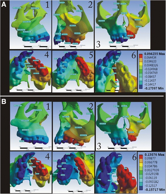
Background: In this finite element (FE) study, the stress distribution and displacement pattern was evaluated in the mid-palatal area and around circum-maxillary sutures exerted by bone-borne palatal expander (BBPE) in comparison with conventional HYRAX rapid palatal expander in unilateral cleft lip and palate.
Methods: Computed tomography scan images of a patient with unilateral cleft palate was used to create a FE model of the maxillary bone along with circum-maxillary sutures. A three-dimensional model of the conventional HYRAX (Hygienic Rapid Expander) expander and custom-made BBPE was created by laser scanning and programmed into the FE model.
Results: With the BBPE, the maximum stress was observed at the implant insertion site, whereas with the conventional HYRAX expander, it was at the dentition level. Among the circum-maxillary sutures, the zygomaticomaxillary suture experienced maximum stress followed by the zygomaticotemporal and nasomaxillary sutures. Displacement in the X-axis (transverse) was highest on the cleft side, and in the Y-axis (antero-posterior), it was highest in the posterior region in the BBPE.
Conclusions: The total displacement was observed maximum in the mid-palatal cleft area in the BBPE, and it produced true skeletal expansion at the alveolar level without any dental tipping when compared with the conventional HYRAX expander.
Keywords: Cleft lip and palate; Finite element method; Microimplant; Rapid palatal expansion.
Figures


Similar articles
-
The effects of micro-implant assisted rapid palatal expansion (MARPE) on the nasomaxillary complex--a finite element method (FEM) analysis.Prog Orthod. 2014 Aug 29;15(1):52. doi: 10.1186/s40510-014-0052-y. Prog Orthod. 2014. PMID: 25242527 Free PMC article.
-
The comparison of biomechanical effects of the conventional and bone-borne palatal expanders on late adolescence with unilateral cleft palate: a 3-dimensional finite element analysis.BMC Oral Health. 2022 Dec 13;22(1):600. doi: 10.1186/s12903-022-02640-1. BMC Oral Health. 2022. PMID: 36514035 Free PMC article.
-
Stress distribution and displacement by different bone-borne palatal expanders with micro-implants: a three-dimensional finite-element analysis.Eur J Orthod. 2014 Oct;36(5):531-40. doi: 10.1093/ejo/cjs063. Epub 2012 Nov 11. Eur J Orthod. 2014. PMID: 23148112
-
Skeletal, dentoalveolar and soft tissue effects of different maxillary expansion appliances in cleft lip/palate patients: A systematic review and frequentist network meta-analysis.J Stomatol Oral Maxillofac Surg. 2025 Sep;126(4S):102312. doi: 10.1016/j.jormas.2025.102312. Epub 2025 Mar 10. J Stomatol Oral Maxillofac Surg. 2025. PMID: 40073935
-
Maxillary orthopedics in the presurgical management of infants with cleft lip and palate.Pediatr Dent. 1995 Nov-Dec;17(7):419-23. Pediatr Dent. 1995. PMID: 8786907 Review. No abstract available.
Cited by
-
Stress Distribution and Displacement of Craniofacial Structures Following Rapid Maxillary Expansion in Different Types of Cleft Palate: A Three-Dimensional FEM Study.Turk J Orthod. 2021 Jun;34(2):77-85. doi: 10.5152/TurkJOrthod.2021.20007. Turk J Orthod. 2021. PMID: 35110155 Free PMC article.
-
Stress and displacement patterns during orthodontic intervention in the maxilla of patients with cleft palate analyzed by finite element analysis: a systematic review.BMC Oral Health. 2023 Feb 13;23(1):93. doi: 10.1186/s12903-023-02714-8. BMC Oral Health. 2023. PMID: 36782289 Free PMC article.
-
Biomechanical behavior of three maxillary expanders in cleft lip and palate: a finite element study.Braz Oral Res. 2024 Apr 8;38:e010. doi: 10.1590/1807-3107bor-2024.vol38.0010. eCollection 2024. Braz Oral Res. 2024. PMID: 38597509 Free PMC article.
-
The three-dimensional finite element model of unilateral complete cleft lip and palate and mechanical analysis of the oral surfaces.Maxillofac Plast Reconstr Surg. 2025 Mar 5;47(1):6. doi: 10.1186/s40902-024-00452-7. Maxillofac Plast Reconstr Surg. 2025. PMID: 40042749 Free PMC article.
-
Finite element analysis of maxillary orthodontic therapies with variable alveolar bone grafts under occlusal forces in patient with unilateral cleft lip and palate.Front Bioeng Biotechnol. 2024 Nov 5;12:1448286. doi: 10.3389/fbioe.2024.1448286. eCollection 2024. Front Bioeng Biotechnol. 2024. PMID: 39564103 Free PMC article.
References
-
- Samuel Berkowitz. Cleft lip and palate—diagnosis and management. 2nd Edition. Berlin: Springer-Verlag; 2006.
-
- Rygh P, Tindlund R. Orthopedic expansion and protraction of the maxilla in cleft palate patients—a new treatment rationale. Cleft Palate J. 1982;19:104–12. - PubMed
-
- Abdoney Use of the Arndt nickel titanium palatal expander in cleft palate cases. J Clin Orthod. 1995;29:496–9. - PubMed
-
- Caniklioglu MN. Use of a nickel titanium palatal expander in cleft-plate cases. J Clin Orthod. 2004;38:374–7. - PubMed
MeSH terms
Substances
LinkOut - more resources
Full Text Sources
Other Literature Sources
Medical
